Model 2616RC | 5 • Troubleshooting and maintenance |
|
|
Table 7. LED definitions (Continued)
LED | Location | Color | Status | Meaning |
|
|
|
|
|
READY | Front panel | Blue | On | Card ready for removal from Patton ForeFront chassis. |
|
|
| Off | Card not ready for removal from Patton ForeFront chassis. |
|
|
|
| Do not remove card from chassis. |
ALARM | Rear blade | Yellow | On solid | A minor alarm condition has been detected. |
|
|
| Flashing | A major alarm condition has been detected. |
|
|
|
|
|
|
|
| Off | The Model 2616RC is operating normally. No action |
|
|
|
| recommended. |
READY | Rear blade | Blue | On | Card ready for removal from Patton ForeFront chassis. |
|
|
|
|
|
|
|
| Off | Card not ready for removal from Patton ForeFront chassis. |
|
|
|
| Do not remove card from chassis. |
|
|
|
|
|
T1/E1 port test modes
The 2616RC offers a number of diagnostics tools to test operation and performance of the T1/E1 ports and line. Diagnostics include DSX1 payload loop and DSX1 line loop.
DSX1 payload loop (dsx1PayloadLoop)
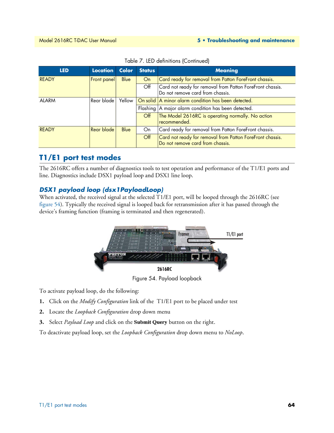
When activated, the received signal at the selected T1/E1 port, will be looped through the 2616RC (see figure 54). Typically the received signal is looped back for retransmission after it has passed through the device's framing function (framing is terminated and then regenerated).
Figure 54. Payload loopback
To activate payload loop, do the following:
1.Click on the Modify Configuration link of the T1/E1 port to be placed under test
2.Locate the Loopback Configuration drop down menu
3.Select Payload Loop and click on the Submit Query button on the right.
To deactivate payload loop, set the Loopback Configuration drop down menu to NoLoop.
T1/E1 port test modes | 64 |