Model 2616RC | 3 • Configuring the |
|
|
2.From the Line Coding
Figure 46. Line Coding pull-down menu with dsx1B8ZS(2) selected
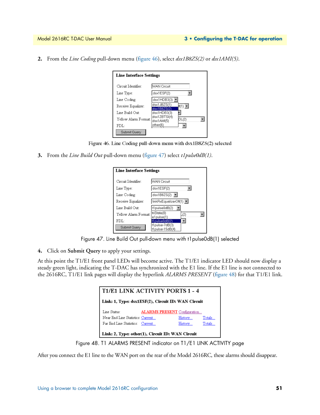
3.From the Line Build Out pull-down menu (figure 47) select t1pulse0dB(1).
Figure 47. Line Build Out pull-down menu with t1pulse0dB(1) selected
4.Click on Submit Query to apply your settings.
At this point the T1/E1 front panel LEDs will become active. The T1/E1 indicator LED should now display a steady green light, indicating the
Figure 48. T1 ALARMS PRESENT indicator on T1/E1 LINK ACTIVITY page
After you connect the E1 line to the WAN port on the rear of the Model 2616RC, these alarms should disappear.
Using a browser to complete Model 2616RC configuration | 51 |