Repair Manual | Macro 5 SLR Camera |
|
|
Strobe PC Board
Caution: Shock Hazard - High Voltage
Note: Use a dump stick to fully discharge the strobe capacitors before attempting to remove or replace the strobe PC board.
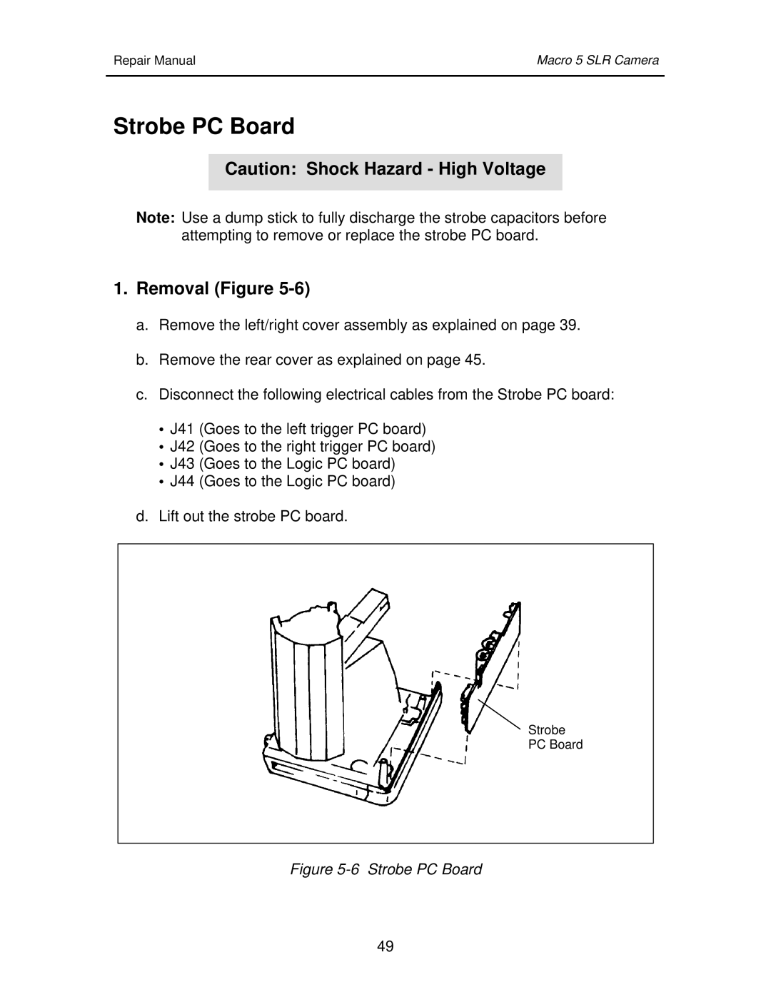
1.Removal (Figure 5-6)
a.Remove the left/right cover assembly as explained on page 39.
b.Remove the rear cover as explained on page 45.
c.Disconnect the following electrical cables from the Strobe PC board:
•J41 (Goes to the left trigger PC board)
•J42 (Goes to the right trigger PC board)
•J43 (Goes to the Logic PC board)
•J44 (Goes to the Logic PC board)
d.Lift out the strobe PC board.
Strobe
PC Board
Figure 5-6 Strobe PC Board
49
