Repair Manual | Macro 5 SLR Camera |
|
|
S1/S2 PC Board
1.Removal (Figure 5-8)
a.Remove the left/right cover assembly as explained on page 39.
b.Using a small pair of diagonal pliers, cut the
c.Disconnect electrical cable J19 from the logic PC board at rear of camera.
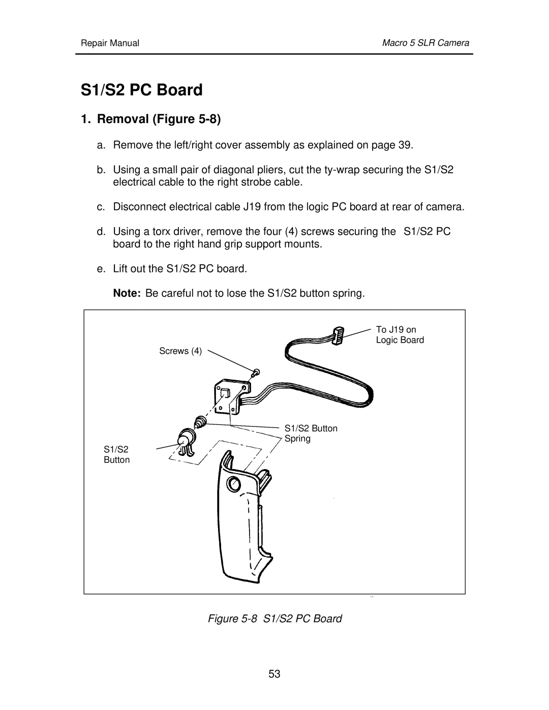
d.Using a torx driver, remove the four (4) screws securing the S1/S2 PC board to the right hand grip support mounts.
e.Lift out the S1/S2 PC board.
Note: Be careful not to lose the S1/S2 button spring.
To J19 on
Logic Board
Screws (4)
S1/S2 Button
Spring
S1/S2
Button
Figure 5-8 S1/S2 PC Board
53