m
Communication Port
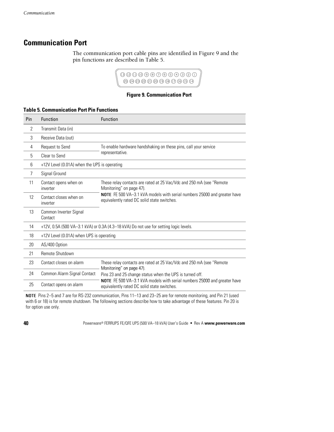
The communication port cable pins are identified in Figure 9 and the pin functions are described in Table 5.
Figure 9. Communication Port
Table 5. Communication Port Pin Functions
o | e | e |
|
|
|
2Transmit Data (in)
3Receive Data (out)
4 | Request to Send | To enable hardware handshaking on these pins, call your service | |
|
| representative. | |
5 | Clear to Send | ||
| |||
|
| ||
6 | +12V Level (0.01A) when the UPS is operating | ||
|
|
| |
7 | Signal Ground |
| |
|
|
| |
11 | Contact opens when on | These relay contacts are rated at 25 Vac/Vdc and 250 mA (see “Remote | |
| inverter | Monitoring” on page 47). | |
|
| NOTEFE 500 | |
12 | Contact closes when on | ||
| inverter | equivalently rated DC solid state switches. | |
|
| ||
|
|
| |
13Common Inverter Signal Contact
14+12V, 0.5A (500
18+12V Level (0.01A) when UPS is operating
20AS/400 Option
21Remote Shutdown
23 | Contact closes on alarm | These relay contacts are rated at 25 Vac/Vdc and 250 mA (see “Remote | |
|
| Monitoring” on page 47). | |
24 | Common Alarm Signal Contact | ||
Pins 23 and 25 change status when the UPS is turned off. | |||
|
| NOTEFE 500 | |
NOTE25 | Contact opens on alarm | ||
equivalently rated DC solid state switches. |
Pins
40 | Powerware® FERRUPS FE/QFE UPS (500 |
