5.Align the five holes in the lift column assembly base with the five holes in the crossbeam. While your assistant holds the lift column assembly firmly in place, put a split lock washer (G) on each of the five
6.Using the hex key (I) provided, begin to tighten the five bolts. Alternate between each one, until the base plate is snug up against the crossbeam. Do not overtighten the bolts.
7.Clip the tie wrap holding the clevis pin in the elevation tube. Remove the clevis and hitch pins. Due to the sensitivity of the lift calibration, do not rotate the elevation tube more than 90 degrees in either direction.
8.Carefully align the mounting holes on the crossbar and elevation tube and slide the elevation tube into the crossbar. Insert the clevis pin (head of the clevis pin should be toward the rear of the treadmill) through both holes and
Note: The lift is elevated to a 1 percent incline for ease of assembly. The functioning and accuracy of your lift mechanism depends on properly installing the clevis and hitch pins.
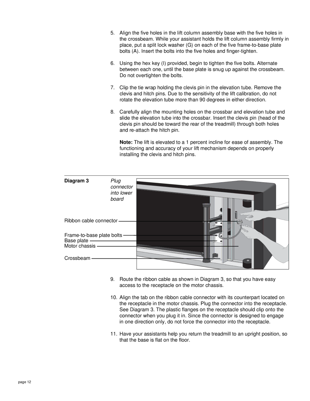
Diagram 3 | Plug |
| connector |
| into lower |
| board |
Ribbon cable connector | |
| |
Base plate |
|
Motor chassis |
|
Crossbeam |
|
9.Route the ribbon cable as shown in Diagram 3, so that you have easy access to the receptacle on the motor chassis.
10.Align the tab on the ribbon cable connector with its counterpart located on the receptacle in the motor chassis. Plug the connector into the receptacle. See Diagram 3. The plastic flanges on the receptacle should clip onto the connector when you plug it in. Since the connector is designed to engage in one direction only, do not force the connector into the receptacle.
11.Have your assistants help you return the treadmill to an upright position, so that the base is flat on the floor.
page 12