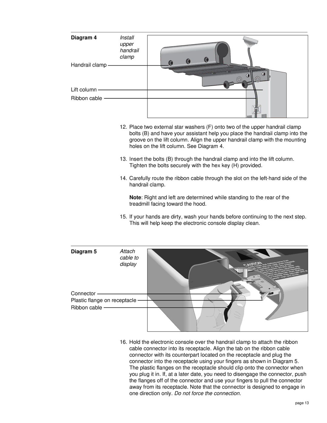
Diagram 4 | Install | |
| upper | |
| handrail | |
| clamp | |
Handrail clamp |
|
|
Lift column |
|
|
Ribbon cable |
|
|
| 12. | Place two external star washers (F) onto two of the upper handrail clamp |
|
| bolts (B) and have your assistant help you place the handrail clamp into the |
|
| groove on the lift column. Align the upper handrail clamp with the mounting |
|
| holes on the lift column. See Diagram 4. |
| 13. | Insert the bolts (B) through the handrail clamp and into the lift column. |
|
| Tighten the bolts securely with the hex key (H) provided. |
| 14. | Carefully route the ribbon cable through the slot on the |
|
| handrail clamp. |
|
| Note: Right and left are determined while standing to the rear of the |
|
| treadmill facing toward the hood. |
| 15. | If your hands are dirty, wash your hands before continuing to the next step. |
|
| This will help keep the electronic console display clean. |
Diagram 5 | Attach |
| cable to |
| display |
Connector
Plastic flange on receptacle Ribbon cable
|
|
|
|
|
|
|
|
| from |
|
|
| |||
|
|
|
|
|
|
| away treadmill |
| |||||||
CAUTIONhands | clothing when |
| allow |
| |||||||||||
|
|
| with |
|
|
|
| ||||||||
| and |
| roller |
|
| power |
|
| |||||||
|
|
| rear |
|
| any |
|
|
|
|
| ||||
| and | As |
|
| NOT |
| with | ||||||||
Keep belt |
|
| . |
|
| DO | unfamiliar | . | |||||||
bed, |
|
|
|
|
|
|
|
|
|
| |||||
inoperation |
|
|
|
|
|
|
|
| treadmill | ||||||
is |
|
| equipment, |
|
|
| this | starting at | |||||||
drivern |
|
| persons |
|
|
| |||||||||
|
|
|
| and |
| near | when | only | |||||||
| children |
| on |
|
|
|
| ||||||||
|
|
|
|
|
| belt |
| belt | |||||||
|
|
|
|
|
|
| INCLINEonto . | ||||||||
|
| operationstraddle.Step | slower | ||||||||||||
|
|
| Always |
|
|
|
| and |
|
| |||||
|
|
|
|
| treadmill |
|
|
|
|
| |||||
|
|
|
| the |
|
| 1mph |
|
|
|
| ||||
|
|
|
| speeds |
|
|
|
|
|
|
| ||||
16.Hold the electronic console over the handrail clamp to attach the ribbon cable connector into its receptacle. Align the tab on the ribbon cable connector with its counterpart located on the receptacle and plug the connector into the receptacle using your fingers as shown in Diagram 5. The plastic flanges on the receptacle should clip onto the connector when you plug it in. If, at a later date, you need to disengage the connector, push the flanges off of the connector and use your fingers to pull the connector away from its receptacle. Note that the connector is designed to engage in one direction only. Do not force the connection.
page 13