Assembly Instructions
To assist you in the assembly of the treadmill, the items in the hardware kit shown in Diagram 1, correspond to a particular letter in the alphabet. These letters appear throughout the assembly instructions. Refer to Diagram 1 while performing the steps below.
To assemble the M9.20/s treadmill, take the following steps:
1.Locate the power switch at the front of the treadmill. Make sure that the power switch is in the OFF position and that the treadmill’s power cord is unplugged. Do not assemble the M9.20/s treadmill if it is plugged in.
CAUTION: Do not try to assemble the treadmill by yourself. Because of the weight of the treadmill and its parts, get additional help from other people before performing the following steps.
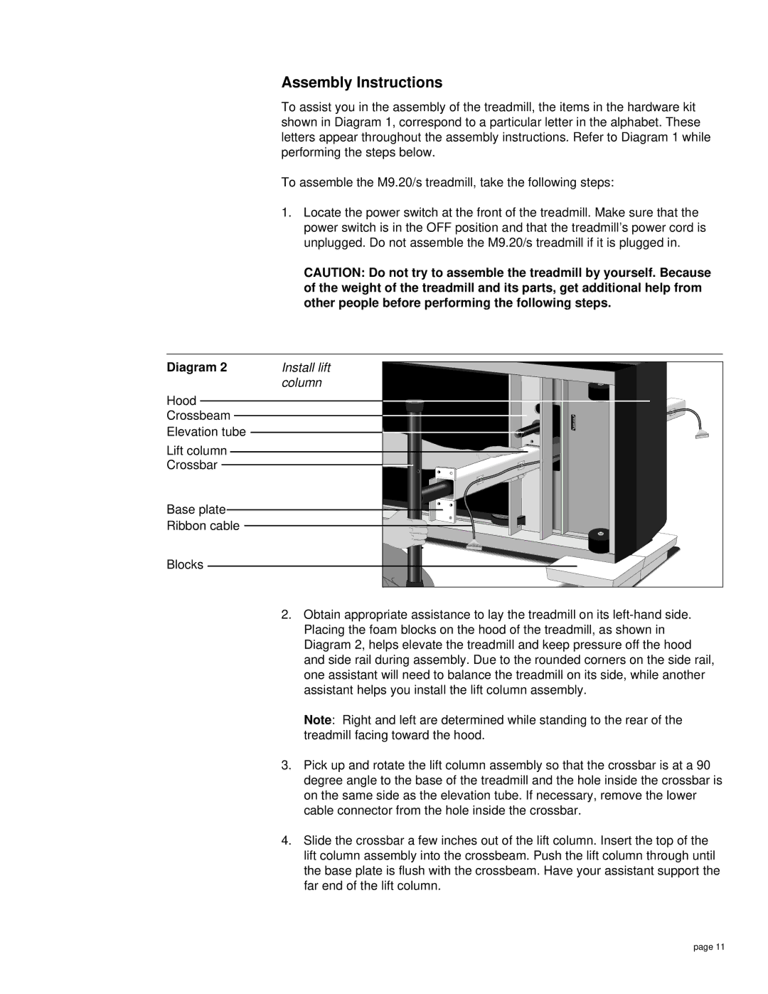
Diagram 2 | Install lift |
| column |
Hood |
|
Crossbeam |
|
Elevation tube |
|
Lift column |
|
Crossbar |
|
Base plate |
|
Ribbon cable |
|
Blocks |
|
2.Obtain appropriate assistance to lay the treadmill on its
Note: Right and left are determined while standing to the rear of the treadmill facing toward the hood.
3.Pick up and rotate the lift column assembly so that the crossbar is at a 90 degree angle to the base of the treadmill and the hole inside the crossbar is on the same side as the elevation tube. If necessary, remove the lower cable connector from the hole inside the crossbar.
4.Slide the crossbar a few inches out of the lift column. Insert the top of the lift column assembly into the crossbeam. Push the lift column through until the base plate is flush with the crossbeam. Have your assistant support the far end of the lift column.
page 11