Intelligent Pressure Scanner User’s Manual
Page
Revision Revision History
Preface
Our Warranty
Merchandise Return Procedures
Our Company
Technical Support
Website and E-Mail Our Firmware Our Publication Disclaimer
Table of Contents
Table of Contents
Table of Contents
Appendices
List of Figures
List of Tables
Chapter General Information
Introduction
Due to a thicker top plate
Model
Description of Instruments
Options
Pressure Ranges
Manifolds and Pressure Connections
Communication Interfaces
This page intentionally left blank
Chapter Installation and Set Up
Safety Considerations
Unpacking and Inspection
Power
Preparation for Use
Environment
Mounting and Module Dimensions
Network Communications Hookup
Ethernet Host Port Hookup
Intelligent Pressure Scanner
Seconds before re-connecting
Ethernet Network Topology
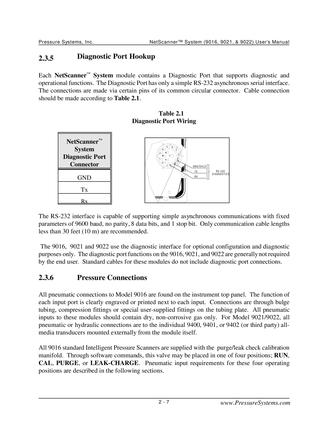
Diagnostic Port Hookup
Diagnostic Port Wiring NetScanner System Connector
Pressure Connections
Page
CAL Mode Inputs
Purge Mode Inputs
Leak Mode Inputs
Supply Air
Excessive pressure may damage the internal solenoids
7 9021 and 9022 Transducer Installation
Connecting or disconnecting external transducers
Installation of 9400, 9401 and 9402 Transducers
Transducer Wiring Installation of All Other Transducers
Trigger Input Signal
Case Grounding
Commands & Responses
Chapter Programming and Operation
Introduction
1.1 TCP/UDP/IP Protocols
Commands
General Command Format
Command Field
Position Field
Page
Responses
Format Field
An Acknowledge with Data response, or
Error Codes
Interpreting Offset Values Re-zero Calibration Adjustment
Functional Command Overview
Interpreting Gain Values Span Calibration Adjustment
Interpreting Engineering Units Output
Startup Initialization
Module Data Acquisition
Page
Delivery of Acquired Data To Host
Network Query and Control Functions
Other Functions
Detailed Command Description Reference
Type Command id Command Function
Power UP Clear Command ‘A’
Command a
Response a
Example
Reset Command ‘B’
Command B
CONFIGURE/CONTROL MULTI-POINT Calibration Command ‘C’
Command C 00 pppp npts ord avg
‘ 00’ is the sub-command index ii for Configure & Start
00 F 3 1
Command C 01 pnt pppp.pppp
Response pppp.pppp pppp.pppp
01 1 -2.5 C 01 2 0.0 C 01 3
Command C
02 w08 w09
‘ 03’ is the sub-command index ii for Abort
Read Transducer Voltages Command ‘V’
Required for normal operation Command Vppppf
Response dddd.. dddd
Converts each internal response datum value from Max.char
V11110
999999 -4.989500 0.005390
Calculate and SET Gains Command ‘Z’
Command Zpppp
Response g.gggg .. g.gggg
Z00F8
000212 1.000269 1.000437 1.000145
Read Transducer A/D Counts Command ‘a’
Converts each internal response datum value from Max.char
A11110
32767.000000 -32700.000000 10.000000
Read HIGH-SPEED Data Command ‘b’
Response aaaabbbbcccc..rrrr
Aaaabbbbcccc .. rrrr
DEFINE/CONTROL Autonomous Host Streams Command ‘c’
Command Ii dddd
Avoid confusing this Configure/Control Autonomous Host
Command
St pppp sync per f num
Autonomous
Packet
Page
With the exception of binary formats 7 and 8, all other
Formats include a leading space in each datum delivered
Each stream packet
00 1 000F 0 1 7 0 c 00 2 00F0 0 2 7 0 c 00 3 FF00 0 4 7
Select other types of data in each stream
Command ‘c’- Sub-command Index 01 Start Streams
Command c 01 st
Example
Command ‘c’- Sub-command Index 02 Stop Streams
Command 02 st
Command ‘c’- Sub-command Index 03 Clear Streams
Command 03 st
02 0 c 03 3 c 01
Command ‘c’ Sub-command Index 04 Return Stream Information
Command c 04 st
Response st pppp sync per f num pro remport ipaddr bbbb
Ffff 0 20 7 32000 1 7002
Command ‘c’ Sub-command Index 05 Select Data in a Stream
Command c 05 st bbbb
Enable DH Temperature Status see bit map below
Bbbb hex data selected for inclusion in each stream packet
Page
05 1
Command c 06 st pro remport ipaddr
‘ 06’ is the sub-command index ii for Select Protocol
Examples
06 0 1
06 0
Calculate and SET Offsets Command ‘h’ Purpose
Hpppp
Gggg .. g.gggg
Description
HF000
0010 0.0020 0.0015
Read Temperature Counts Command ‘m’
For normal operation Command mppppf
Converts each internal response datum value from Max. char
M11110
20692.000000 19783.000000 19204.000000
Read Temperature Voltages Command ‘n’
N11110
53013 0.541698 0.503633
Read Module Status Command ‘q’
Hhhh
Firmware Version, as hex value
Auto UDP Broadcast@Reset , as hex state
Q00
9016
Q07
Read HIGH-PRECISION Data Command ‘r’
Command rppppf
R11110
234000 0.989500 1.005390
Read Transducer Temperature Command ‘t’
Tppppf
Dddd.. dddd
T11110
21.234000 20.989500 21.005390
Read Internal Coefficients Command ‘u’
Command ufaacc-cc
Converts each internal value from Max. char
Diagnostic functions
Span Cal Adjustment gain term
Dynamic EU Conversion coefficient c0
Dynamic EU Conversion coefficient c1
Transducer Coefficient Description Datum Type
EU Pressure Conversion scaler default=1.0
Temperature Gain Reference Coefficient
Other Coefficients Description Datum Type
Gain=1 Reference Coefficient 9021/9022 only
Download Internal Coefficients Command ‘v’
Command vfaacc-ccdddd..dddd
Converts each datum parameter value ‘ dddd’ from Max. char
User Defined Field
Page
V00800-01 0.000
V01101
SET/DO Operating OPTIONS/FUNCTIONS Command ‘w’
Command wiidd eeee
Set Number of Channels in Module default =16 for
Description ‘q’ read Index
Disable Automatic Shifting of Calibration Valve in ‘h’
Set Cal Valves to RUN or Leak Position default
Set Cal Valves to CAL/RE-ZERO or Purge Position Chart
Set Number of A/D Samples to Average . default =
Disable Host Response/Stream Total Size Prefix
Enable Host Response/Stream Total Size Prefix 2-byte
Set Maximum Temperature Alarm Set Point in N C
Set Thermal Update Scan Interval per eeee as decimal
Description ‘q’ read
Position Example
W1200
W0C01
Network Query UDP/IP Command ‘psi9000’
Command Psi9000
Ipadr, ethadr, sernum, mtype
Query all modules on the network
RE-BOOT Module UDP/IP Command ‘psireboot’
Command Psireboot ethadr
Psireboot 00-E0-8D-00-00-01
None
Command psirarp ethadr
Psirarp 00-E0-8D-00-00-01
Obsolete Commands
Page
Chapter Calibration
Page
Figures 4.1 Pneumatic Diagrams of the Calibration Manifold
Re-zero Calibration
Re-zero Calibration Valve Control
Description 9016 9021/9022 Command
Re-zero Calibration Summary
Span Calibration
Span Calibration Valve Control
Description Command 9021/9022
Span Calibration Summary
Description Command 9021/9022 Command
CAL
Integrated Multi-Point Calibration Adjustment
Multi-Point Calibration Valve Control
Multi-Point Calibration Summary
Page
When using the 9021/9022 with digitally compensated Model
9021/9022 Analog Calibration
Transducers
Setup
9022 Voltage Input Connections
Calibration Procedure
CoefNew = CoefOld * 1 + Vapplied V9021 ÷ Vapplied Example
Gain9021/9022 Command
Description
Coefficient Command
Reference 9021/9022 Coefficient Command
Coefficient Storage
Page
Page
Page
Page
Line Pressure Precautions
Chapter Service
Maintenance
Exploded View of 9016
Modules are field replaceable, but are not field repairable
Top Plate
Top Plate 1000+ Prior to S/N
Common Maintenance
Component Cross Reference Section 9016 9021 9022
Maintenance kit PSI P/N
S901-0200000000with
Lubricants included
Module Disassembly
Electronic Circuit Board Replacement
Scanner Out of Housing
3.1 PC-206 Amplifier/Multiplexer Board
3.2 PC-242 Amplifier/Multiplexer Board 9021 only
3.3 PC-280 Ethernet Microprocessor/A-D Board 9016, 9021
PC-280 Board
Section PCBs Outside the Housing PCBs Apart
Replacement of Transducers
Top View of DH200
Calibration Valve Solenoid Replacement
Solenoid in Module
Replacement of O-Rings
6.1 DH200 Pressure Transducer O-Ring Replacement
DH200 Transducer O-Ring Replacement
Tubing Plate O-Ring Replacement
Adapter Plate O-Ring Replacement
Calibration Manifold Piston O-Ring Replacement
Solenoid Valve O-Ring Replacement
9022 Excitation Trim
PC-317 Board Trim Potentiometer and Jumper
Page
Upgrading Module Firmware
Upgrading Firmware Via Host TCP/IP Port
This page intentionally left blank
Chapter Troubleshooting Guide
Ethernet Module Troubleshooting
Checking Module Power-Up Sequence
Checking Module TCP/IP Communications
Module IP Address Assignment
Page
When placed in Dynamic addressing mode, through the TCP/IP
Modules should be using them, please contact your network
Verifying Host TCP/IP Communications
Zero and Gain Calibration Troubleshooting
Page
Page
User Software
Unified Startup Software Nuss User’s Manual
Chapter
Start-up Software
This page intentionally left blank
All Commands Quick Reference
Appendix a
UDP/IP
NetScanner System Response Error Codes
Undefined Command Received
Appendix B
This page intentionally left blank
Cable Diagrams
Appendix C
Description Applicable Models
NetScanner System Ethernet Interface Cable
NetScanner System Ethernet Interface Cable
Cable 9400/9021 D-Shell Cable
Cable 9400/9022 Circular Connector Cable
To Series 27 Interface Cable 9021
To Series 27 Interface Cable
Calibration Cable
Third-Party Sensor Interface Cable
This page intentionally left blank
Mounting Dimensions
Appendix D
Mounting Dimensions
Mounting Dimensions
Mounting Dimensions
Appendix E
NetScanner System Range Codes
Psid 12 psi
Psid 12 psi 375 psi 150 psi 650 psi 850psi Psia 25 psi
This page intentionally left blank
Appendix F
NetScanner System/9000 Series Products
Model Purpose
This page intentionally left blank
Appendix G
Binary Bit Map
This page intentionally left blank
Headquarters/Factory European Office