English
Step 1: Basic Recorder Connections (continued)
|
|
|
| DIGITAL |
| HDMI |
|
|
|
| DIGITAL | HDMI |
|
|
|
|
|
| ANTENNA INPUT |
|
|
|
|
| ANTENNA INPUT |
|
| ||
|
| ANTENNA INTERCONNECT CABLE | DIGITAL ANTENNA |
|
| OUT |
|
| ANTENNA INTERCONNECT CABLE | DIGITAL ANTENNA |
| OUT |
|
|
|
|
|
|
|
|
|
|
|
|
| ||||
|
| (OPTIONAL, REFER TO MANUAL) | LOOP THROUGH |
|
| Y |
| (OPTIONAL, REFER TO MANUAL) | LOOP THROUGH | Y | PB |
| ||
|
|
|
|
|
|
|
|
|
|
|
| |||
| TO TV | EXT1 | TO VCR/SAT | EXT2 |
| L |
| TO TV | EXT1 | TO VCR/SAT | EXT2 | L |
|
|
|
|
|
|
|
|
|
|
|
|
|
|
| PR |
|
|
|
|
|
|
| R |
|
|
|
|
| R |
|
|
TO TV ANTENNA | ANALOG |
|
|
| AUDIO | CO |
|
|
|
| AUDIO |
| COAXIAL | |
|
|
|
|
|
|
| DIGITAL | |||||||
INPUT | ANTENNA INPUT |
|
|
| OUT | OUT | DIGI |
|
|
| OUT | OUT | OUT | IN |
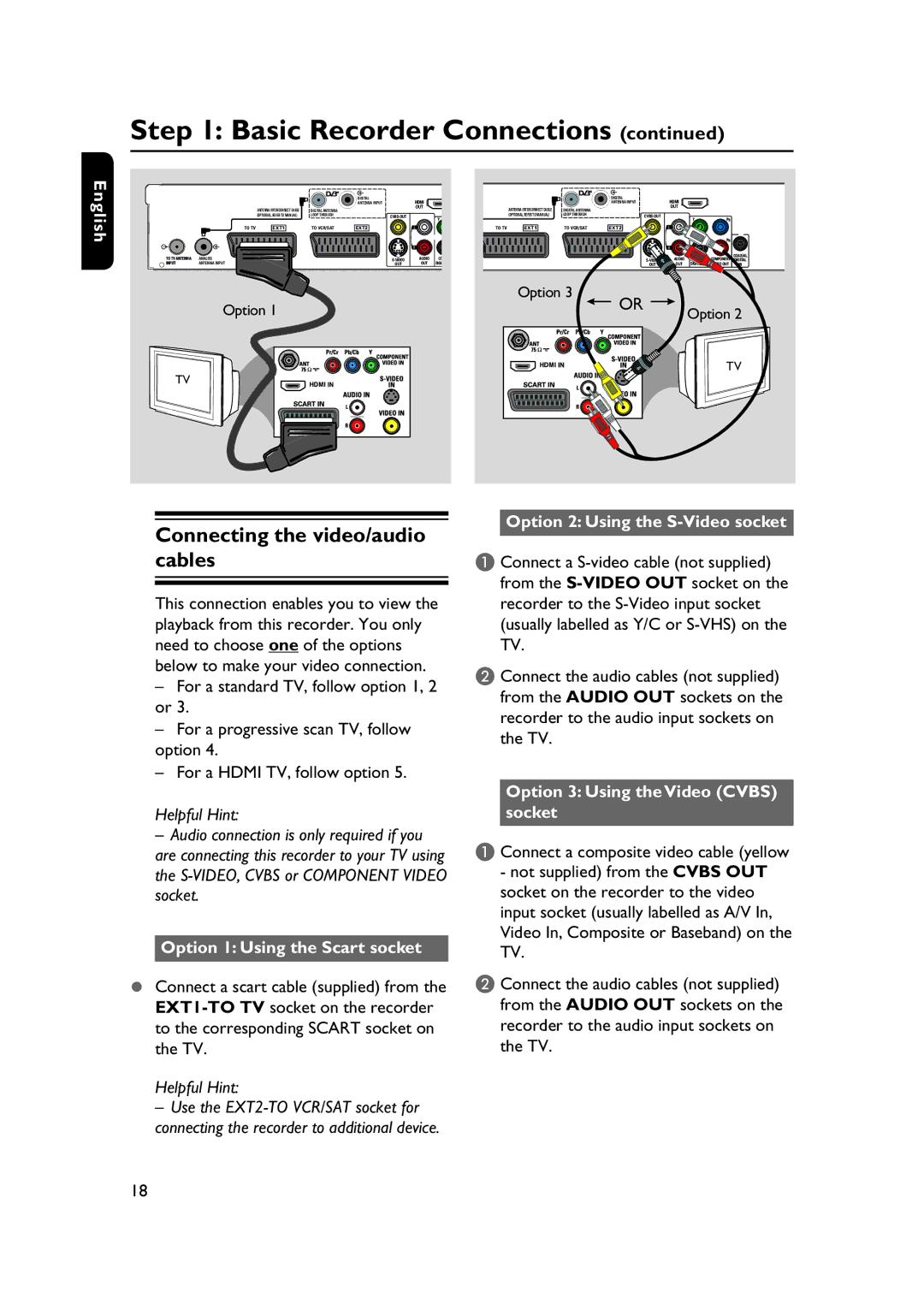
Option 1
TV
Option 3 |
|
OR | Option 2 |
| |
| TV |
Connecting the video/audio cables
This connection enables you to view the playback from this recorder. You only need to choose one of the options below to make your video connection.
–For a standard TV, follow option 1, 2 or 3.
–For a progressive scan TV, follow option 4.
–For a HDMI TV, follow option 5.
Helpful Hint:
–Audio connection is only required if you are connecting this recorder to your TV using the
Option 1: Using the Scart socket
Connect a scart cable (supplied) from the
Helpful Hint:
–Use the
Option 2: Using the S-Video socket
A Connect a
B Connect the audio cables (not supplied) from the AUDIO OUT sockets on the recorder to the audio input sockets on the TV.
Option 3: Using the Video (CVBS) socket
A Connect a composite video cable (yellow
-not supplied) from the CVBS OUT socket on the recorder to the video input socket (usually labelled as A/V In, Video In, Composite or Baseband) on the TV.
B Connect the audio cables (not supplied) from the AUDIO OUT sockets on the recorder to the audio input sockets on the TV.
18