English
Step 2: Optional Connections (continued)
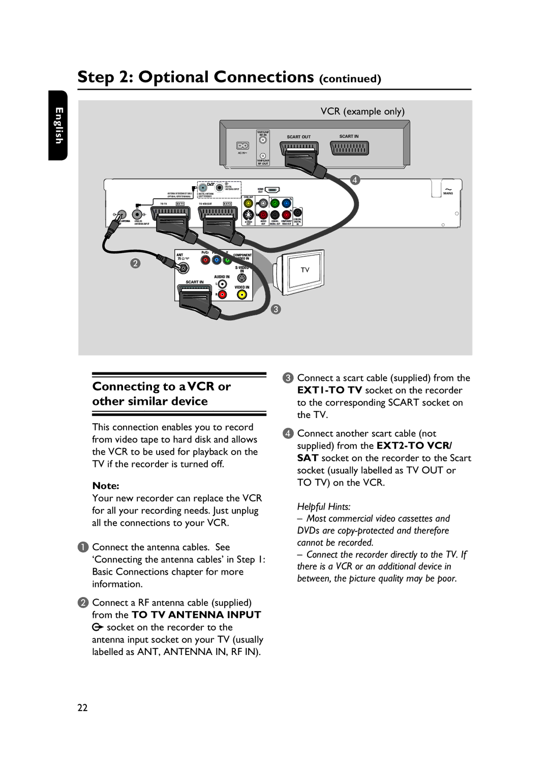
VCR (example only)
|
|
|
| DIGITAL |
|
|
|
| ANTENNA INPUT |
|
| ANTENNA INTERCONNECT CABLE | DIGITAL ANTENNA |
|
|
| (OPTIONAL, REFER TO MANUAL) | LOOP THROUGH | |
TO TV | EXT1 | TO VCR/SAT | EXT2 | |
TO TV ANTENNA | ANALOG |
|
| |
INPUT | ANTENNA INPUT |
|
| OUT |
VHF/UHF |
|
|
|
|
RF IN |
| SCART OUT | SCART IN | |
|
| |||
VHF/UHF |
|
|
|
|
RF OUT |
|
|
|
|
|
|
|
| D |
HDMI |
|
|
|
|
OUT |
|
|
| MAINS |
|
|
|
| |
| Y | PB |
|
|
L |
|
|
|
|
|
| PR |
|
|
R |
|
|
|
|
AUDIO | COAXIAL | COMPONENT | COAXIAL |
|
DIGITAL |
| |||
OUT | DIGITAL OUT VIDEO OUT | IN |
| |
B
TV
C
Connecting to a VCR or other similar device
This connection enables you to record from video tape to hard disk and allows the VCR to be used for playback on the TV if the recorder is turned off.
Note:
Your new recorder can replace the VCR for all your recording needs. Just unplug all the connections to your VCR.
A Connect the antenna cables. See ‘Connecting the antenna cables’ in Step 1: Basic Connections chapter for more information.
B Connect a RF antenna cable (supplied) from the TO TV ANTENNA INPUT ![]() socket on the recorder to the antenna input socket on your TV (usually labelled as ANT, ANTENNA IN, RF IN).
socket on the recorder to the antenna input socket on your TV (usually labelled as ANT, ANTENNA IN, RF IN).
C Connect a scart cable (supplied) from the
D Connect another scart cable (not supplied) from the
Helpful Hints:
–Most commercial video cassettes and DVDs are
–Connect the recorder directly to the TV. If there is a VCR or an additional device in between, the picture quality may be poor.
22