201 specifications
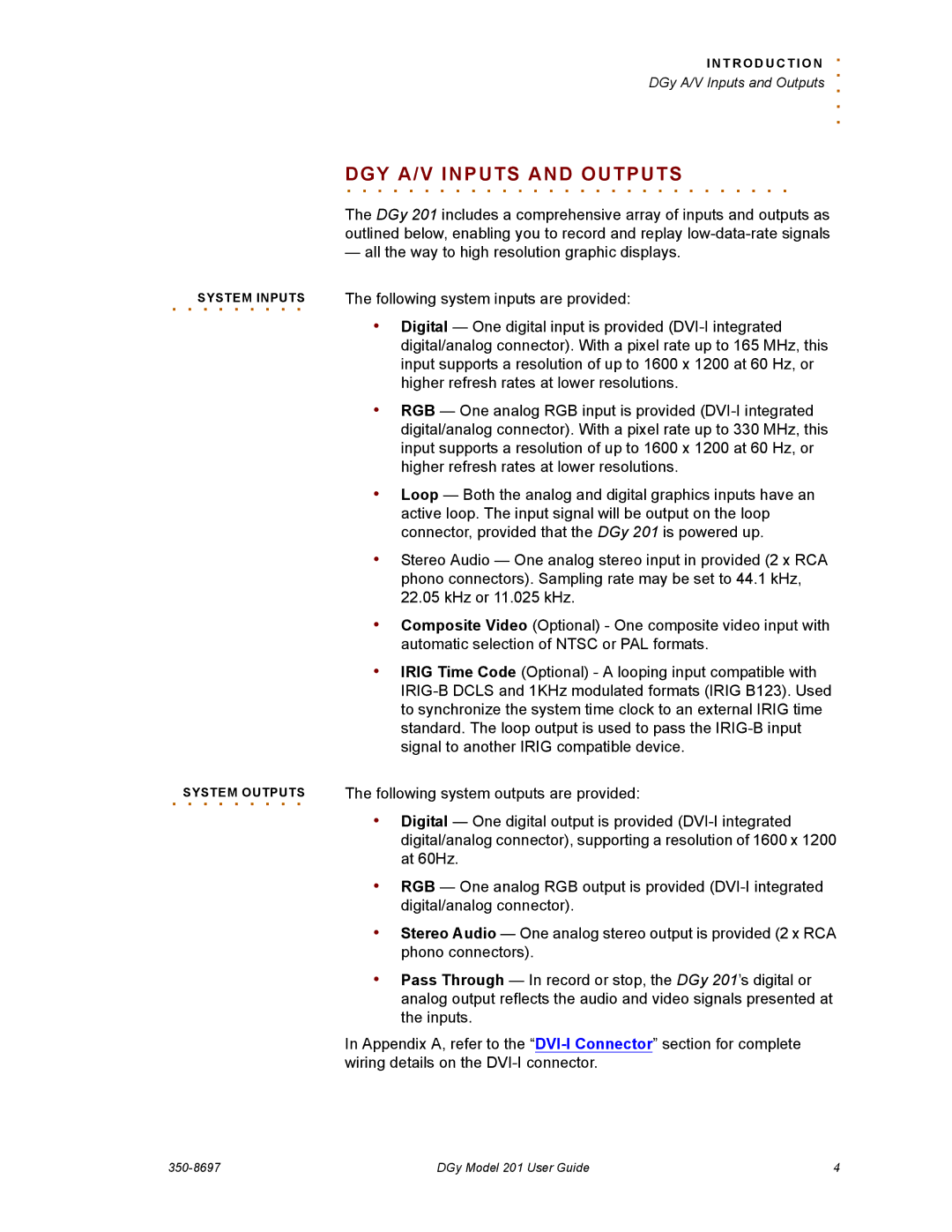
The RGB Spectrum 201 is a cutting-edge solution designed for advanced video wall processing and multi-display control, specifically tailored for command and control environments, media production, and other professional applications. Renowned for its high performance and flexibility, the Spectrum 201 sets a new standard in image processing and content management.One of the standout features of the RGB Spectrum 201 is its ability to support a vast range of input sources. It accommodates HDMI, DisplayPort, DVI, and even legacy signals, ensuring seamless integration of various devices into a single cohesive system. This versatility makes it suitable for diverse environments, such as control rooms, broadcast studios, and corporate presentations.
The device's processing capabilities are equally impressive. The Spectrum 201 features advanced scaling and video windowing technologies that allow users to display multiple sources simultaneously on large video walls without sacrificing image quality. This level of detail is further enhanced by its high resolution, enabling crisp and clear visuals even when scaled across expansive displays.
In terms of usability, the RGB Spectrum 201 boasts a user-friendly interface that simplifies the control and management of content. Users can easily switch between sources, adjust layouts, and configure displays through an intuitive software platform or a dedicated hardware controller. This ease of use is a significant benefit in fast-paced scenarios where decision-making and response times are critical.
The built-in redundancy and reliability of the Spectrum 201 are essential features for mission-critical applications. It incorporates failover mechanisms to ensure uninterrupted performance, which is critical for control centers that rely on constant access to vital information.
Additionally, the RGB Spectrum 201 is compatible with various network protocols, facilitating integration into existing IT infrastructures. This connectivity ensures that users can access and share content easily across different platforms, enhancing collaboration and information dissemination.
In summary, the RGB Spectrum 201 embodies a blend of advanced features, robust technology, and user-friendly design, making it an ideal choice for professionals seeking an effective and reliable solution for video processing and multi-display management. With its impressive capabilities, the Spectrum 201 not only meets but exceeds the demands of modern visual communication.
