Wire Sizes
NOTE: Make sure the proper extension cord is used and is in good condition.
The use of any extension cord will cause some loss of power. To keep this to a min- imum and to prevent overheating and motor
Extension Cord | Gauge |
Length | (A.W.G) |
|
|
16 | |
14 | |
|
|
Check Motor Rotation
Place the motor on your workbench or on the floor. Standing clear of the motor shaft, plug the motor cord into a properly grounded outlet. Notice the rotation of the shaft. As you look directly at the motor shaft it should be turning in the clockwise
direction. ![]() If the motor shaft is turning clockwise, remove the plug from the power outlet and continue the assem- bly procedures. If the motor is turning counterclockwise, remove the plug from the power outlet and contact
If the motor shaft is turning clockwise, remove the plug from the power outlet and continue the assem- bly procedures. If the motor is turning counterclockwise, remove the plug from the power outlet and contact
Unpacking and Checking Contents
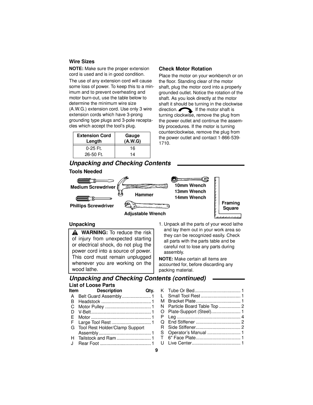
Tools Needed
Medium Screwdriver |
| 10mm Wrench |
| 13mm Wrench | |
| Hammer | |
| 14mm Wrench | |
|
| |
Phillips Screwdriver |
| Framing |
| Square | |
|
| |
| Adjustable Wrench |
|
Unpacking
![]() WARNING: To reduce the risk of injury from unexpected starting or electrical shock, do not plug the power cord into a source of power. This cord must remain unplugged whenever you are working on the wood lathe.
WARNING: To reduce the risk of injury from unexpected starting or electrical shock, do not plug the power cord into a source of power. This cord must remain unplugged whenever you are working on the wood lathe.
1.Unpack all the parts of your wood lathe and lay them out in your work area so they can be recognized easily. Check all parts with the parts table and be careful not to lose any parts during assembly.
NOTE: Make certain all items are accounted for, before discarding any packing material.
Unpacking and Checking Contents (continued)
List of Loose Parts
Item | Description | Qty. | K | Tube Or Bed | 1 | |
A | Belt Guard Assembly | 1 | L | Small Tool Rest | 1 | |
B | Headstock | 1 | M | Bracket Plate | 1 | |
C | Motor Pulley | 1 | N | Particle Board Table Top | 2 | |
D | ............................................... | 1 | O | 1 | ||
E | Motor | ............................................... | 1 | P | Leg | 4 |
F | Large Tool Rest | 1 | Q | End Stiffener | 2 | |
G | Tool Rest Holder/Clamp Support |
| R | Side Stiffener | 2 | |
| Assembly | 1 | S | Operator’s Manual | 1 | |
H | Tailstock and Ram | 1 | T | 6" Face Plate | 1 | |
J | Rear Foot | 1 | U | Live Center | 1 | |
9