FOR YOUR SAFETY
Installation, Operation
3. DO NOT use electrical switches
Some objects will catch fire or explode when placed close to heater
Page
SECTION 13 Wiring
TABLE OF CONTENTS
SECTION 16 Troubleshooting
SECTION 8 Multiburner Configuration
Page
TABLE OF FIGURES
Page
1 of
Product Approval
1.1 Manpower Requirements
SECTION 1 HEATER SAFETY
1.3 Safety Labels and Their Placement
Figure 1 Bottom and Back Panel Label Placement
SECTION 1 HEATER SAFETY
Figure 2 Control Side Label Placement
Description
91033200
Refer to appropriate Material Safety Data Sheets MSDS
SECTION 2 INSTALLER RESPONSIBILITY
2.1 Low Level User Instructions
2.2 Corrosive Chemicals
SECTION 3 CLEARANCES TO COMBUSTIBLES
Some objects will catch fire or explode when placed close to heater
Fire Hazard
3.1 Required Clearances to Combustibles
FIGURE 3 LINEAR & DOUBLE LINEAR, HORIZONTAL MOUNTS
3.2 Clearances Data - Linear and Double Linear
Model
HE40ST
HE15ST
FIGURE 8 UNDERSHIELD
HE30DL
HE20ST
FIGURE 10 U-TUBE, HORIZONTAL MOUNT
3.3 Clearances Data - U-Tube
HE15UT
HE20UT
HE15U
FIGURE 14 U-TUBE, OPPOSITE 45 TILT
FIGURE 15 U-TUBE, PROTECTIVE GRILLE
FIGURE 16 U-TUBE, VENTING
Reflector Support Strap, Wire Form & #8 x 3/4 Screw Flex Gas Line Tee
SECTION 4 MAJOR COMPONENT DESCRIPTIONS
Assembly
Coupling Assembly with Lock Reflector End Cap
SECTION 5 GENERAL SUSPENSION DETAILS
Wear protective gear during installation, operation and service
Severe Injury Hazard
Secure burner to burner tube with bolts and lockwashers
Typical Suspension Details
Figure 17 Critical Hanger Placement
Side View
Bow Shackle
6.1 Linear Standard Parts List
SECTION 6 LINEAR & DOUBLE LINEAR HEATER INSTALLATION
Wear protective gear during installation, operation and service
Cut/Pinch Hazard
Figure 18 Linear General Assembly Overview
HE15ST f HE20ST HE25ST f HE30ST HE35ST HE40ST f
Figure 19 Linear Layout Overview
HE45ST HE50ST f
Description
6.2 Double Linear Standard Parts List
HE30DL
HE40DL
Bird Screen
Figure 20 Double Linear General Assembly Overview
HE30DL f
Figure 21 Double Linear Layout Overview
HE40DL
HE50DL
Step 6.4 Coupling and Tube Assembly
Step 6.3 Burner Tube Installation
Open
Closed
Step 6.4.2 Coupling and Tube Assembly Continued
Step 6.4.1 Coupling and Tube Assembly Continued
± 50 mm
Correct Slide Bar dimensions
Description
Step 6.5 Tube Clamp Package Installation
Tube Clamp Package
01318901
Fire Hazard Support reflector with reflector hanger and support strap
Step 6.6 Reflector Installation
Reflector must not touch tube
Description
Option B
Wire Form
Option A
Option B
Part Number
Description
01329600
01329700
7.1 U-tube Standard Parts List
SECTION 7 U-TUBE HEATER INSTALLATION
Wear protective gear during installation, operation and service
Cut/Pinch Hazard
Description
PVC coating must be removed prior to installation
HE15UT
HE20UT
Figure 22 BLACKHEAT HE
U-tube Assembly Overview
HE15UT g HE20UT g HE25UT HE30UT HE35UT g HE40UT
Figure 23 BLACKHEAT HE U-tube Layout Overview
HE45UT g HE50UT
Step 7.3 Burner Tube and Fan Tube Installation
Step 7.2 U-tube Hanger Placement
Offset mounting hole must be to the top Weld Spot Fan Tube
Burner Tube
Step 7.4 U-tube Support Bracket Assembly Installation
Step 7.3.1 Tube Clamp Package Installation
U-tube, Standard
U-tube, Opposite
Step 7.5.1 Coupling and Tube Assembly Continued
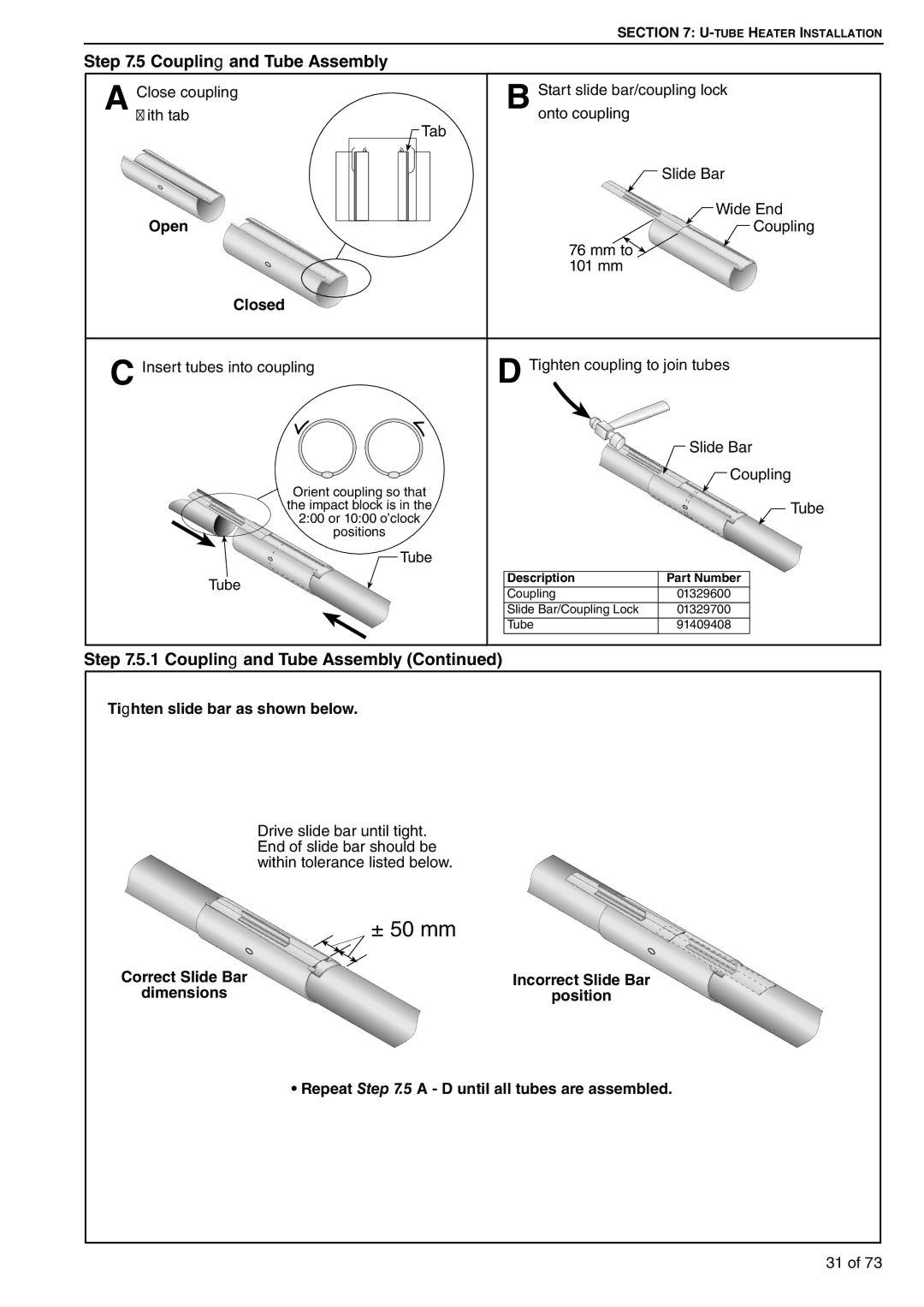
Step 7.5 Coupling and Tube Assembly
Correct Slide Bar dimensions
± 50 mm
Step 7.7 U-tube Installation
Step 7.6 Tube Installation
Description
01329600
Fire Hazard Support reflector with reflector hanger and support strap
Step 7.8 Reflector Installation
Reflector must not touch tube
Weld Spot
Option A
Option B
Option B
Option A
8.1 Initial Assembly
SECTION 8 MULTIBURNER CONFIGURATION & INSTALLATION
Figure 24 Multiburner Damper Flange Installation
Wear protective gear during installation, operation and service
Figure 25 Typical Manifold Layout Linear and U-Tube Configuration
Step 9.2 Standard Fan Assembly
SECTION 9 BURNER & FAN INSTALLATION Step 9.1 Burner Installation
For details, see Page 21, Step
9.4 Linear & U-tube Fan Installation
9.3 IP55 Fan Assembly
Fan Assembly
Step 9.5.1 Double Linear Fan Installation Continued
Step 9.5 Double Linear Fan Installation
Step 9.7 Condensate Drain Assembly
Wear protective gear during installation, operation and service
SECTION 10 OPTIONAL HEATER ACCESSORIES
Cut/Pinch Hazard
Edges are sharp
Step 10.1.1 Bracket Installation
10.1 Reflector Side Extension Installation
Step 10.1.2 Side Reflector Installation
Extension Bracket
Step
10.2 U-Tube Cover Installation
Step
Step
Description
Step 10.3.2 Frame Shield Installation
Description
Description
Step 10.4.3 Grille Installation
Step 10.4.2 Grille End Cap Installation
Step 10.5.2 Fastener Installation
10.5 Sports Hall Guard Installation
Step 10.5.1 Grille Installation
Step 10.5.3 Mesh Guard Connection
10.6.2 Undershield Installation
10.6 Undershield Installation 10.6.1 Hanger Installation
10.6.3 Adjust Undershield Height
10.7 Wall Mounting
10.7.1 Hardware Installation
Figure 26 U-tube Horizontal
Figure 27 U-tube Angle Mounted
11.3 Flue Installation
Heaters must be installed according to the installation manual
SECTION 11 VENTING AND FRESH AIR SUPPLY
Carbon Monoxide Hazard
Figure 29 Individual Flue Connection Detail
Figure 30 Flue Connection Dimensions
11.6 Outside Combustion Air Supply
11.6.1 Air Supply Requirements
11.7 Common Duct
Figure 31 Air Supply with Flue Configurations
51 of
Use only 1000 mm long connector of 1/2 or 3/4 nominal ID
Flex gas line can crack when twisted
Gas can leak if piping is not installed properly
SECTION 12 GAS PIPING
when attaching gas hose
Figure 32 Gas Connection with Stainless Steel Flex Connector
INCORRECT POSITIONS WRONG INSTALLATION
CORRECT POSITIONS
Electrical Shock Hazard Disconnect electric before service
SECTION 13 WIRING
13.1 Typical External Wiring Diagram Linear or U-Tube
DANGER
13.3 Typical External Wiring Diagram Double Linear Option
13.2 Typical External Wiring Diagram Double Linear Option
13.4 Typical External Wiring Diagram Multiburner
Fuse
56 of
13.5 Internal Wiring Diagram
before service
heater before service
during installation
disconnect switch may
14.2 Testing
14.1.2 Heater Lockout Indicator by Volt Free Connector
14.3 Commissioning Multiburner
14.4 System Checks
15.1 Annual Procedure
15.1.3 Tube and Reflector Maintenance
15.1.2 Burner and Fan Removal Maintenance
SECTION 15 SERVICING INSTRUCTIONS
15.4 Maintenance Checklist
15.3.5 Pressure Switch
15.3.1 Electrode Figure 34 Burner Cup Position
15.3.4 Automatic Flame Control Unit
Outside Air Inlet
Vent Pipe
Tubes
Gas Line
Keep all flammable
SECTION 16 TROUBLESHOOTING
objects, liquids and
vapors the minimum
16.1 Troubleshooting Flow Chart Linear, Double Linear
and U-Tube
64 of
Troubleshooting Flow Chart Linear, Double Linear and U-Tube
16.2 Troubleshooting Flow
Chart Multiburner
66 of
Troubleshooting Flow Chart Multiburner
Combustion Chamber
16.3 Manifold Gas Pressure Setting
ntrol Chamber
Manometer 6 5 4 3 2 1 0 1 2 3 4 5
DANGER
SECTION 17 REPLACEMENT PARTS
68 of
L, T2
17.1.1 Screw and Gasket Replacement Package P/N
17.1 Replacement Packages
17.1.2 Viewer Window Replacement Package P/N
17.1.3 Door Gasket Replacement Package P/N
18.2 Heater Specifications 18.2.1 Sequence Controller
SECTION 18 SPECIFICATIONS 18.1 Material Specifications
18.3 Venting Specifications 18.3.1 Fans
18.4 Suspension Specifications
18.7 Double Linear Heater
18.6 Linear Heater
18.8 U-tube Heater
Figure 35 BLACKHEAT HE Linear and U-tube Specifications
18.9 Burner Specifications
18.9.1 Standard Burner Specifications
Models
Page
Page
Maintain
Some objects will catch fire or explode when placed close to
clearance
the side