BLACKHEAT® HE INSTALLATION OPERATION AND SERVICE MANUAL
Step 6.4.1 Coupling and Tube Assembly (Continued)
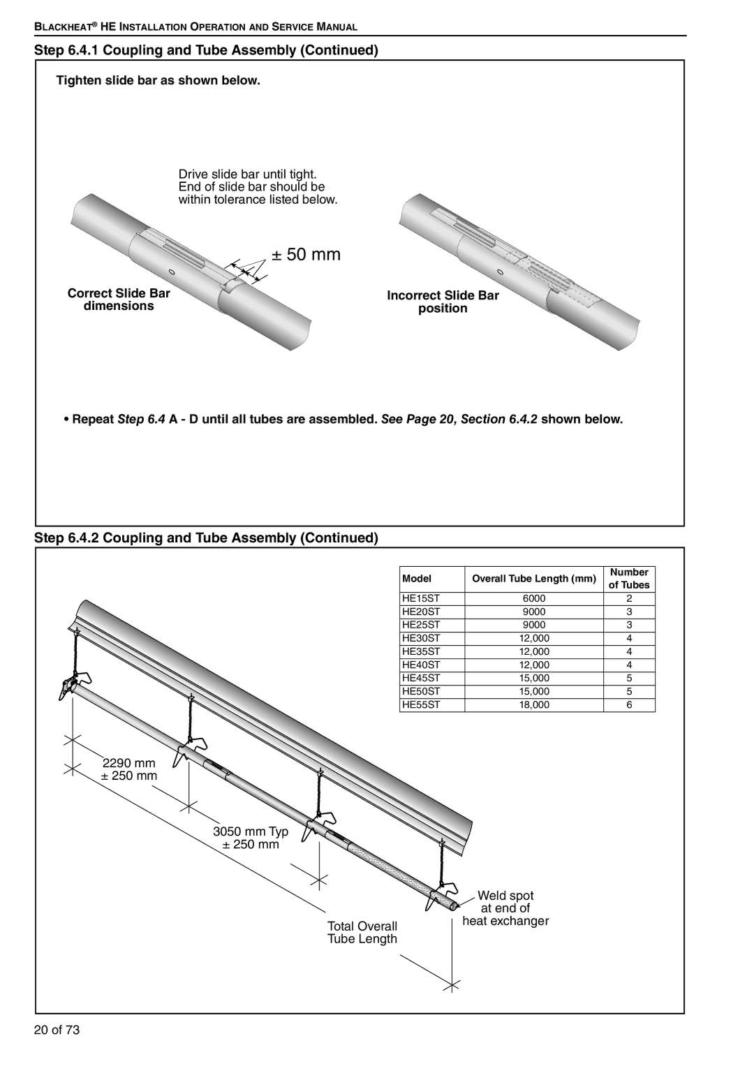
Tighten slide bar as shown below.
Drive slide bar until tight. End of slide bar should be within tolerance listed below.
± 50 mm
Correct Slide Bar
dimensions
Incorrect Slide Bar
position
• Repeat Step 6.4 A - D until all tubes are assembled. See Page 20, Section 6.4.2 shown below.
Step 6.4.2 Coupling and Tube Assembly (Continued)
Model | Overall Tube Length (mm) | Number | |
of Tubes | |||
|
| ||
HE15ST | 6000 | 2 | |
HE20ST | 9000 | 3 | |
HE25ST | 9000 | 3 | |
HE30ST | 12,000 | 4 | |
HE35ST | 12,000 | 4 | |
HE40ST | 12,000 | 4 | |
HE45ST | 15,000 | 5 | |
HE50ST | 15,000 | 5 | |
HE55ST | 18,000 | 6 | |
2290 mm |
|
| |
± 250 mm |
|
| |
3050 mm Typ |
|
| |
± 250 mm |
|
| |
| Weld spot |
| |
| at end of |
| |
Total Overall | heat exchanger |
| |
Tube Length |
|
| |
20 of 73 |
|
|