SECTION 6: LINEAR & DOUBLE LINEAR HEATER INSTALLATION
Step 6.6.1 Reflector, U-clip and Reflector Support Installation
The pictorial drawings of the heater construction in Section 6 are schematic only and provide a general guideline of where hangers, reflector supports and
To ensure proper expansion and contraction movement of the reflectors, a combination of
supports are used. The positioning of reflector supports and
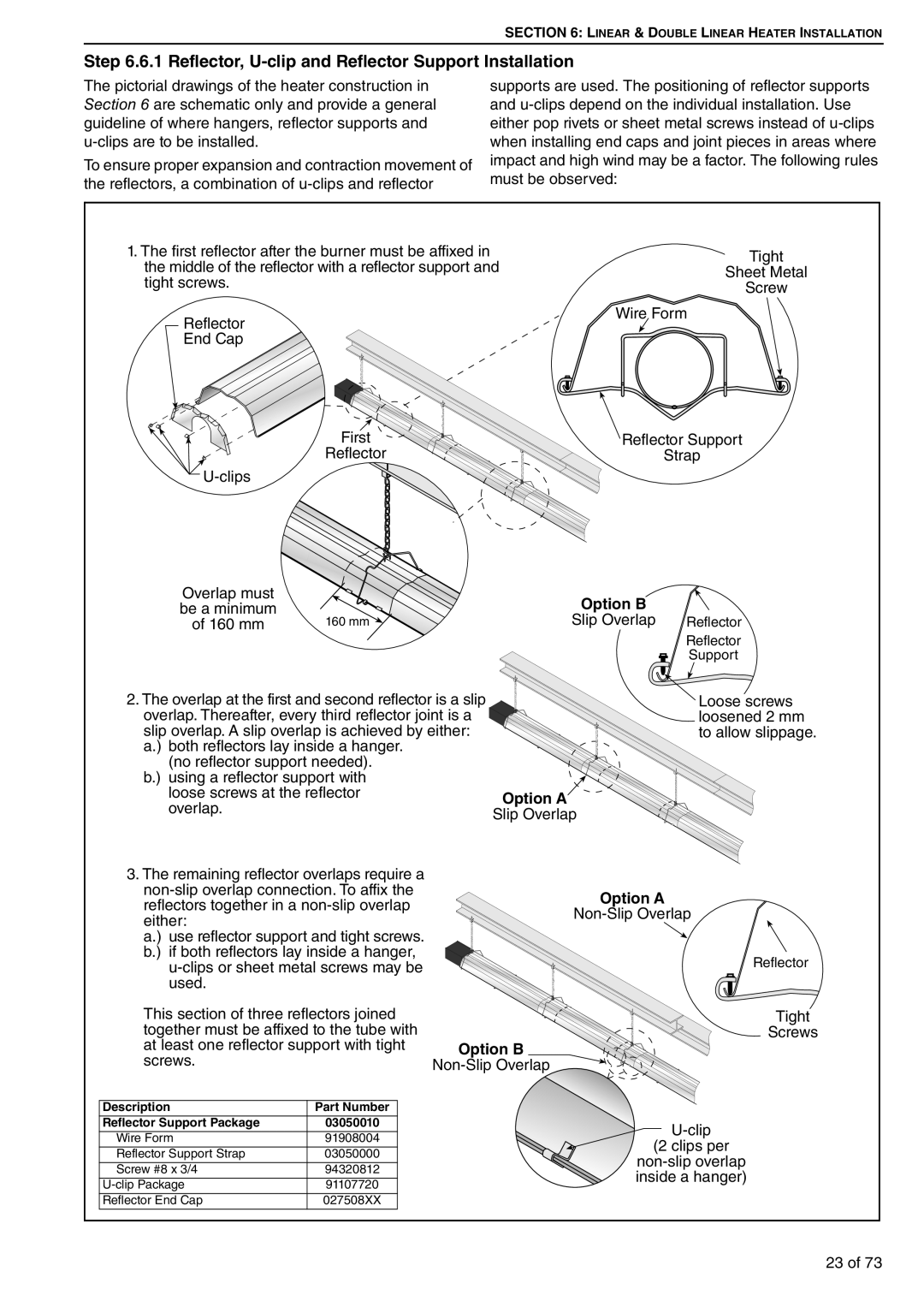
1.The first reflector after the burner must be affixed in the middle of the reflector with a reflector support and tight screws.
End
Reflector
![]()
Overlap must |
|
be a minimum | 160 mm |
of 160 mm |
Tight
Sheet Metal
Screw
Wire Form
![]() Reflector Support
Reflector Support
Strap
Option B
Slip Overlap Reflector
Reflector
Support
2.The overlap at the first and second reflector is a slip overlap. Thereafter, every third reflector joint is a slip overlap. A slip overlap is achieved by either: a.) both reflectors lay inside a hanger.
(no reflector support needed). b.) using a reflector support with
loose screws at the reflector overlap.
![]() Loose screws loosened 2 mm to allow slippage.
Loose screws loosened 2 mm to allow slippage.
Option A
Slip Overlap
3.The remaining reflector overlaps require a
a.) use reflector support and tight screws. b.) if both reflectors lay inside a hanger,
This section of three reflectors joined together must be affixed to the tube with at least one reflector support with tight screws.
Option B
Option A
![]() Reflector
Reflector
Tight
Screws
Description | Part Number |
Reflector Support Package | 03050010 |
Wire Form | 91908004 |
Reflector Support Strap | 03050000 |
Screw #8 x 3/4 | 94320812 |
91107720 | |
Reflector End Cap | 027508XX |
23 of 73