Dual Channel High Power Digital Motor Controller
AX2550/2850
Revision History
Date Version Changes
Revision History
AX2550/2850 Motor Controller User’s Manual
Section
Section
Self-Test Display
104
124
152
AX2500/2850 Quick Start
What you will need
Locating Switches, Wires and Connectors
AX2500/2850 Quick Start
Connecting to the Batteries and Motors
Connecting to the Batteries and Motors
Connecting the R/C Radio
Using the Power Control Wire
Power Control input connected to Action
Powering On the Controller
Powering On the Controller
Button Operation
Prog and Set button status Function
Default Controller Configuration
Checking and Changing Configurations
Default Controller Configuration
Parameter Default Values Letter
Connecting the controller to your PC using Roborun
Obtaining the Controller’s Software Revision Number
Obtaining the Controller’s Software Revision Number
Exploring further
AX2500/2850 Motor Controller Overview
Product Description
Technical features
Technical features
Low Power Consumption
High Efficiency Motor Power Outputs
Optical Encoder Inputs AX2850 only
Data Logging Capabilities
Advanced Safety Features
Sturdy and Compact Mechanical Design
Connecting Power
Connecting Power and Motors to the Controller
Connecting Power
Controller Power
Connecting Power and Motors to the Controller
Controller Power
Two
Powering the Controller using the Motor Batteries
Using a Backup Battery
Powering the controller from the Motor Batteries
Power Fuses
Wire Length Limits
Electrical Noise Reduction Techniques
Power Regeneration Considerations
Electrical Noise Reduction Techniques
Overvoltage Protection
Using the Controller with a Power Supply
Undervoltage Protection
Using the Controller with a Power Supply
Connecting Power and Motors to the Controller
Input Command Modes
General Operation
Basic Operation
Basic Operation
Selecting the Motor Control Modes
Open Loop, Separate Speed Control
Open Loop, Mixed Speed Control
General Operation
Close Loop Position Control
Closed Loop Speed Control
Selecting the Motor Control Modes
Setting Continuous High Amps
Current Limit Settings
Continuous and Extended Current Limitation
Temperature-Based Current Limitation
Temperature-Based Current Limitation
Setting Continuous High Amps Extended Safe Amps
Regeneration Current Limiting
Surge Current Protection
Programmable Acceleration
Programmable Acceleration
Command Control Curves
Exponentiation curves
Left / Right Tuning Adjustment
Left / Right Tuning Adjustment
Exponentiation Parameter Value Selected Curve
Emergency Shut Down Using Controller Switches
Parameter Value Speed Adjustment
Emergency Stop using External Switch
Emergency Stop using External Switch
Inverted Operation
Self-Test Mode
Special Use of Accessory Digital Inputs
Using the Inputs to Activate the Buffered Output
Self-Test Mode
General Operation
AX2500/2850 Connections
Connecting Sensors and Actuators to Input/Outputs
AX2500/2850 Connections
Connecting Sensors and Actuators to Input/Outputs
AX2500/2850’s Inputs and Outputs
Signal Type Use Activated
AX2500/2850’s Inputs and Outputs
Pin Wire Input or Number Color Output Signal Description
List and Pin Assignment
Connecting devices to Output C
Connecting devices to Output C
Connecting devices to Output D
Connecting external Mosfet and load to Output D
Connecting Switches or Devices to Input E
Connecting Switches or Devices to Input F
Connecting Switches or Devices to EStop/Invert Input
Show how to wire the switch to this input
Connecting Position Potentiometers to Analog Inputs
Connecting Position Potentiometers to Analog Inputs
Connecting Tachometer to Analog Inputs
Potentiometer wiring in Position mode
Connecting External Thermistor to Analog Inputs
Connecting External Thermistor to Analog Inputs
Temp oC
Resistance kOhm
Using the Analog Inputs to Monitor External Voltages
NTC
Connecting User Devices to Analog Inputs
Connecting User Devices to Analog Inputs
Measured volts = controller reading + 128 * 0.255
Internal Heatsink Temperature Sensors
Internal Voltage Monitoring Sensors
Temperature Conversion C Source Code
Temperature Conversion C Source Code
Connecting Sensors and Actuators to Input/Outputs
Use of the LED Display
Normal Fault Condition LED Messages
Use of the LED Display
Motor Direction Status
Normal and Fault Condition LED Messages
Possible Display Motor Comment
Fault Messages
Fault Messages
No Control
Self-Test Display
Emergency Stop
Mode Description
Mode Description
Operation
Typical Wiring
Selecting the R/C Input Mode
Operation
Connector I/O Pin Assignment R/C Mode
Connector I/O Pin Assignment R/C Mode
Pin Input or Number Signal Output Description
Input Circuit Description
Supplied Cable Description
Supplied Cable Description
Cabling to R/C Receiver using Full Opto-Isolation
Cabling to R/C Receiver with Partial Opto-Isolation
Cabling to R/C Receiver with Partial Opto-Isolation
Powering the Radio from the controller
Partial opto-isolation with Channel 3 electrical diagram
Powering the Radio from the controller
Wiring for powering R/C radio from controller
Operating the Controller in R/C mode
Joystick position vs. pulse duration default values
Transmitter/Receiver Quality Considerations
Reception Watchdog
Reception Watchdog
Joystick Deadband Programming
Command Control Curves
Left/Right Tuning Adjustment
Joystick Calibration
Automatic Joystick Calibration
Activating the Accessory Outputs
Activating the Accessory Outputs
Data Logging in R/C Mode
Using Channel 3 to activate accessory outputs
Data Logging in R/C Mode
Operation
Use and benefits of RS232
Serial RS-232 Controls Operation
Use and benefits of RS232
Connector I/O Pin Assignment RS232 Mode
Must be wired to pin 13 or pin
Must be wired to pin
Serial RS-232 Controls and Operation
Cable configuration
Cable configuration
Extending the RS232 Cable
Bits/s, 7-bit data, 1 Start bit, 1 Stop bit, Even Parity
Communication Settings
Establishing Manual Communication with a PC
Entering RS232 from R/C or Analog mode
Data Logging String in R/C or Analog mode
Establishing Manual Communication with a PC
Roboteq v1.7 02/01/05 s
RS232 Mode if default
RS232 Commands Set
Set Motor Command Value
Set Accessory Outputs
Query Power Applied to Motors
RS232 Commands Set B7F
A3F
Query Amps Consumed by Motors
Query Analog Inputs
Query Heatsink Temperatures
Query Battery Voltages
RS232 Commands Set
Query Digital Inputs
Read parameter
Read and Modify Controller Settings
Modify parameter
Optical Encoder Commands
Commands Acknowledge and Error Messages
Reset Controller
Apply Parameter Changes
Command Acknowledgement
Command Error
RS-232 Watchdog
Watchdog time-out
RS232 Accessible Parameter Table
RS232 Accessible Parameter Table
PID
Automatic Switching from RS232 to RC Mode
Automatic Switching from RS232 to RC Mode
Analog and R/C Modes Data Logging String Format
Data Logging Cables
Data Logging Cables
Decimal to Hexadecimal Conversion Table
Dec Hex
Decimal to Hexadecimal Conversion Table
106
Analog Control and Operation
Analog Control and Operation
Connector I/O Pin Assignment Analog Mode
Unused
Connecting a Potentiometer
Connecting to a Voltage Source
Connecting to a Voltage Source
Selecting the Potentiometer Value
= U/R = 5V / 1000 Ohms = 0.005A = 5mA
Analog Deadband Adjustment
Analog Deadband Adjustment
Under Voltage Safety
Power-On Safety
Data Logging in Analog Mode
Data Logging in Analog Mode
Modified Analog cable with RS232 output data logging for PC
114
Closed Loop Position Mode
Selecting the Position Mode
Position Sensor Selection
Closed Loop Position Mode
Sensor Mounting
Potentiometer wiring
Using Optical Encoders in Position Mode
Potentiometer wiring
Sensor and Motor Polarity
Important Safety Warning
Adding Safety Limit Switches
Safety limit switches interrupting power to motors
Using Current Limiting as Protection
Control Loop Description
Control Loop Description
PID tuning in Position Mode
Closed Loop Speed Mode
Selecting the Speed Mode
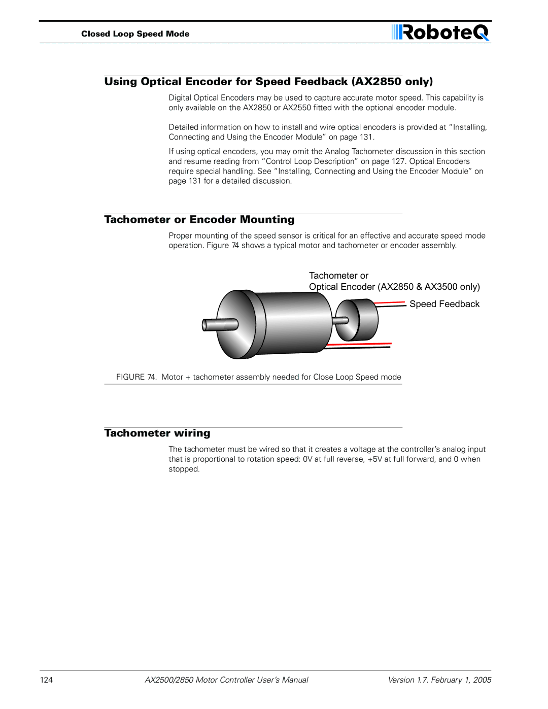
Using Optical Encoder for Speed Feedback AX2850 only
Tachometer wiring
Closed Loop Speed Mode
Tachometer or Encoder Mounting
Speed Sensor and Motor Polarity
Speed Sensor and Motor Polarity
Adjust Offset and Max Speed
AX2500/2850 Motor Controller User’s Manual 127
PID tuning in Speed Mode
PID algorithm used in Speed mode
PID tuning in Speed Mode
130
Optical Incremental Encoders Overview
Installing Connecting Using Encoder Module
Optical Incremental Encoders Overview
Installing, Connecting and Using the Encoder Mod
Recommended Encoder Types
Installing the Encoder Module
Installing the Encoder Module
Pulse Frequency in Hz = RPM / 60 * PPR
Position of Encoder Module on Controller’s main board
Connecting the Encoder
Connecting the Encoder
Pin Name Cable Color
Voltage Levels, Thresholds and Limit Switches
Motor Encoder Polarity Matching
Wiring Optional Limit Switches
Wiring Optional Limit Switches
Using the Encoder Module to Measure Distance
Using the Encoder to Measure Speed
Using the Encoder to Measure Speed
Using the Encoder to Track Position
Distance = Destination Counter value / Divider
RS232 Communication with the Encoder Module
RS232 Encoder Command Set
Read Encoder Counter
?q or Q n
?Q0
Set/Reset Encoder Counters and Destination Registers
RS232 Encoder Command Set
Read Speed
Or !Q n
Read Distance
Read Encoder Limit Switch Status
Read Speed/Distance
Read / Modify Encoder Module Registers and Parameters
Switch Value
?w or ?W
Address Parameter Description Size Access
Controller replies, value is
Register Description
Encoder Hardware ID code
Switch Status
Speed or Distance 1 or
Counter Read/Write Mailbox
Counter 1
Counter Read Data Format
Speed 1
Time Base 1
Encoder Threshold
Encoder Testing and Setting Using the PC Utility
FFFFFF15
Encoder Module Parameters Setting
Encoder Testing and Setting Using the PC Utility
Exercising the Motors
Updating the Encoder Software
Viewing Encoder Data
Programming using built-in Switches and Display
Configuring Controller using Switches
Programming Methods
Entering Programming Mode
Configuring the Controller using the Switches
Changing parameters
Restoring factory defaults
Special Case of Joystick Calibration
Exiting the Parameter Setting Mode
Programmable Parameters List
Order Letter Description Possible Values default Pages
Programmable Parameters List
158
Downloading and Installing the Utility
Using the Roborun Configuration Utility
System Requirements
Connecting the Controller to the PC
Using the Roborun Configuration Utility
Roborun Frame, Tab and Menu Descriptions
Roborun Frame, Tab and Menu Descriptions
Parameter Selection and Setting, and Special Functions
File and Program Management Commands
Getting On-Screen Help
Loading, Changing Controller Parameters
Controls Settings
Power Settings
Left/Right Adjust
Acceleration Setting
Effect of Digital Inputs
Deadband
Analog or R/C Specific Settings
Joystick Timing
Viewing the Parameters Summary
Closed Loop Parameters
Running the Motors
Optical Encoder Operation
Optical Encoder Operation
Run/Stop Button
Motor Power setting
Measurement
Real-Time Strip Chart Recorder
Input Status and Output Setting
Running the Motors
Transmit and Receive Data
Logging Data to Disk
Connecting a Joystick
Parameter Header Data type/range Measured Parameter
Viewing and Logging Data in Analog and R/C Modes
Operating the AX2500/2850 over a Wired or Wireless LAN
Loading and Saving Profiles to Disk
Operating the AX2500/2850 over a Wired or Wireless LAN
Roboserver screenshot when idle
Updating the Controller’s Software
Creating Customized Object Files
Objectmaker creates controller firmware with custom defaults
Creating Customized Object Files
176
Mechanical Dimensions
Mechanical Specifications
Mechanical Dimensions
Mounting Considerations
Mechanical Specifications
Thermal Considerations
Wire Dimensions
Weight
Wire Dimensions
Wire Gauge Outside Diameter Color Length
180