| Europa User Guide |
|
| Europa MIDI Implementation | ||||||||||
|
|
|
|
|
|
|
|
|
|
|
|
|
| |
|
|
|
|
|
|
|
|
|
|
|
|
|
| |
|
| Byte # | Valid | Name | Description |
|
|
|
|
| ||||
|
|
| range |
|
|
|
|
|
|
|
|
|
|
|
|
| 49 | Switch data (nibble 1) | Set LFO 1’s waveshape (only one bit is valid): |
|
| ||||||||
|
|
|
|
| Bits |
|
| Set to 0 |
|
| ||||
|
|
|
|
| Bit 3 - |
|
|
|
|
| 1 - Triangle |
|
| |
|
|
|
|
| Bit 2 – |
|
|
|
|
| 1 - Sawtooth |
|
| |
|
|
|
|
| Bit 1 – |
|
|
|
|
| 1 - Square wave |
|
| |
|
|
|
|
|
|
|
|
|
| |||||
|
|
|
|
| Bit 0 – |
|
|
|
|
| 1 - Random waveform |
|
| |
|
|
|
|
|
|
|
|
|
|
|
| |||
|
| 50 | Switch data (nibble 2) | Set PWM/VCO MOD enables: |
|
| ||||||||
|
|
|
|
| Bits |
|
| Set to 0 |
|
| ||||
|
|
|
|
| Bit 3 – |
|
|
|
|
| 1 - PWM ENV 1 |
|
| |
|
|
|
|
| Bit 2 – |
|
|
|
|
| 1 - PWM LFO |
|
| |
|
|
|
|
| Bit 1 – |
|
|
|
|
| 1 - VCO 1 MOD |
|
| |
|
|
|
|
| Bit 0 – |
|
|
|
|
| 1 - VCO 2 MOD |
|
| |
|
|
|
|
|
|
|
| |||||||
|
| 51 | Switch data (nibble 3) | Set VCO 1 waveform(s): |
|
| ||||||||
|
|
|
|
| Bits |
|
| Set to 0 |
|
| ||||
|
|
|
|
| Bit | 3 | – |
|
| - 1=Triangle wave, 0=Disabled |
|
| ||
|
|
|
|
| Bit | 2 | – |
|
| - 1=Sawtooth wave, 0=Disabled |
|
| ||
|
|
|
|
| Bit | 1 | – |
|
|
| - 1=Pulse wave, 0=Disabled |
|
| |
|
|
|
|
|
|
|
|
|
| |||||
|
|
|
|
| Bit | 0 | – |
|
| - 1=Square wave, 0=Disabled |
|
| ||
|
|
|
|
|
|
|
|
| ||||||
|
|
|
|
| NOTE: Bits 0 & 1 (pulse and square waves) cannot |
|
| |||||||
|
|
|
|
| be enabled simultaneously! Setting it this way will |
|
| |||||||
|
|
|
|
| cause the entire patch to be ignored. |
|
| |||||||
|
| 52 | Switch data (nibble 4) | Set VCO 2 waveform(s): |
|
| ||||||||
|
|
|
|
| Bits |
|
| Set to 0 |
|
| ||||
|
|
|
|
| Bit | 3 | – |
|
| - 1=Triangle wave, 0=Disabled |
|
| ||
|
|
|
|
| Bit | 2 | – |
|
| - 1=Sawtooth wave, 0=Disabled |
|
| ||
|
|
|
|
| Bit | 1 | – |
|
|
| - 1=Pulse wave, 0=Disabled |
|
| |
|
|
|
|
|
|
|
|
|
| |||||
|
|
|
|
| Bit | 0 | – |
|
| - 1=Noise, 0=Disabled |
|
| ||
|
| 53 | Switch data (nibble 5) | Set VCF/Sync setting(s): |
|
| ||||||||
|
|
|
|
| Bits |
|
| Set to 0 |
|
| ||||
|
|
|
|
| Bits |
|
| |||||||
|
|
|
|
|
|
|
|
|
|
|
| 00 = Invalid |
|
|
|
|
|
|
|
|
|
|
|
|
|
| 01 = High pass |
|
|
|
|
|
|
|
|
|
|
|
|
|
| 10 = Low pass |
|
|
|
|
|
|
|
|
|
|
|
|
|
| 11 = Bandpass |
|
|
|
|
|
|
| Bit | 1 | – |
|
| - 1=VCO |
|
| ||
|
|
|
|
| Bit | 0 | – |
|
| - 1=VCO |
|
| ||
|
| 54 | Switch data (nibble 6) | Set filter mode setting(s): |
|
| ||||||||
|
|
|
|
| Bits |
|
| Set to 0 |
|
| ||||
|
|
|
|
| Bits |
|
| |||||||
|
|
|
|
|
|
|
|
|
|
|
| 00 = Invalid |
|
|
|
|
|
|
|
|
|
|
|
|
|
| 01 = Negative |
|
|
|
|
|
|
|
|
|
|
|
|
|
| 10 = Positive |
|
|
|
|
|
|
|
|
|
|
|
|
|
| 11 = Invalid |
|
|
|
|
|
|
| Bit | 1 | – |
|
| 1=VCF Modified by ENV 1 |
|
| ||
|
|
|
|
| Bit | 0 | – |
|
| 1=VCF Modified by ENV 2 |
|
| ||
|
|
|
|
|
|
|
|
|
|
|
|
|
|
|
|
|
|
|
|
|
|
|
|
|
|
|
|
|
|
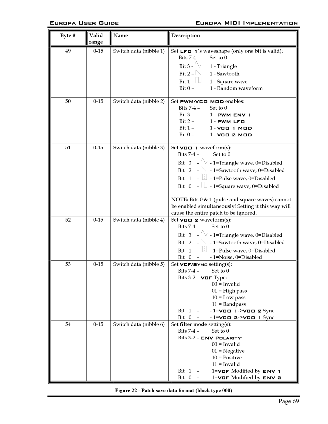
Figure 22 - Patch save data format (block type 000)
Page 69