CONNECTIONS | 3 |
AC Power (mains) Cord Connection |
|
|
|
|
|
|
|
|
|
|
|
|
|
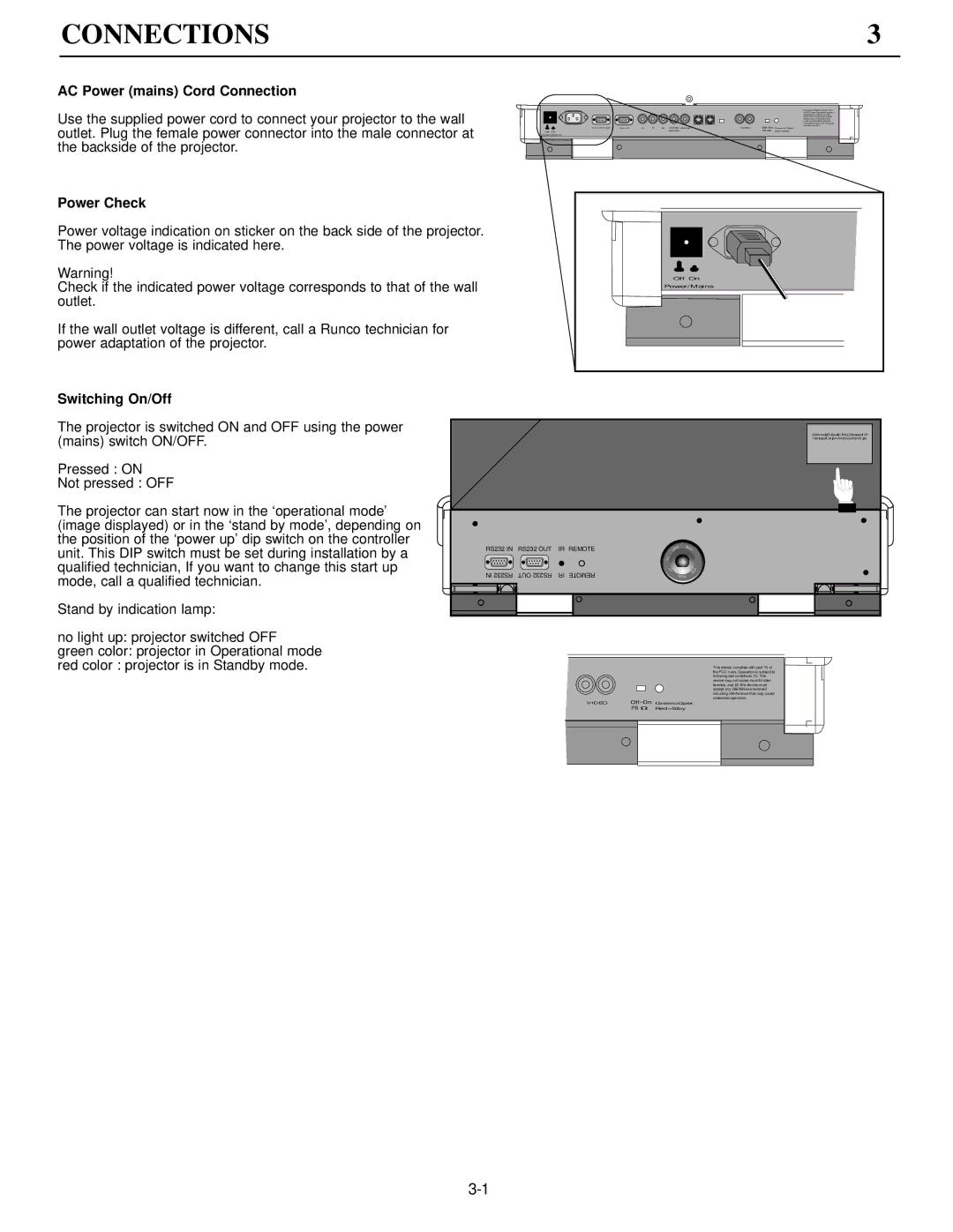
Use the supplied power cord to connect your projector to the wall |
|
| Comm Port | Port 3 | R | G | B | Comp/ VSYNC | VIDEO | Green=Oper. | This device complies with part 15 of | ||
|
| undesired operation. | |||||||||||
|
|
|
|
|
|
|
|
|
|
|
|
| the FCC rules. Operation is subject to |
|
|
|
|
|
|
|
|
|
|
|
|
| following two conditions (1). This |
|
|
|
|
|
|
|
|
|
|
|
|
| device may not cause harmful inter- |
|
|
|
|
|
|
|
|
|
|
|
|
| ference, and (2) this device must |
|
|
|
|
|
|
|
|
|
|
|
|
| accept any interference received |
outlet. Plug the female power connector into the male connector at |
|
|
|
|
|
|
|
|
|
|
|
| including interference that may cause |
| Off On |
|
|
|
|
| HSYNC |
|
|
| Red=Stby |
| |
|
| Power/Mains |
|
|
|
|
|
|
|
|
|
| |
the backside of the projector. |
|
|
|
|
|
|
|
|
|
|
|
|
|
Power Check |
|
|
|
|
|
|
|
|
|
|
|
|
|
Power voltage indication on sticker on the back side of the projector. |
|
|
|
|
|
|
|
|
|
|
|
|
|
The power voltage is indicated here. |
|
|
|
|
|
|
|
|
|
|
|
|
|
Warning! |
|
|
|
|
|
|
| Off On |
|
|
| ||
Check if the indicated power voltage corresponds to that of the wall |
|
|
|
|
|
| Power/Mains |
|
|
| |||
outlet. |
|
|
|
|
|
|
|
|
|
|
|
|
|
If the wall outlet voltage is different, call a Runco technician for |
|
|
|
|
|
|
|
|
|
|
|
|
|
power adaptation of the projector. |
|
|
|
|
|
|
|
|
|
|
|
|
|
Switching On/Off |
|
|
|
|
|
|
|
|
|
|
|
|
|
The projector is switched ON and OFF using the power |
|
|
|
|
|
|
|
|
|
|
|
| ;laksdjf;lkdj;flkj;lkssd;fl |
(mains) switch ON/OFF. |
|
|
|
|
|
|
|
|
|
|
|
| ;'lakjdl;kjlnmfoomnfl;jk |
Pressed : ON |
|
|
|
|
|
|
|
|
|
|
|
|
|
Not pressed : OFF |
|
|
|
|
|
|
|
|
|
|
|
|
|
The projector can start now in the ‘operational mode’ |
|
|
|
|
|
|
|
|
|
|
|
|
|
(image displayed) or in the ‘stand by mode’, depending on |
|
|
|
|
|
|
|
|
|
|
|
|
|
the position of the ‘power up’ dip switch on the controller |
|
|
|
|
|
| TV | S | 8 |
|
|
|
|
unit. This DIP switch must be set during installation by a | RS232 IN | RS232 OUT | IR REMOTE |
|
|
| L |
| mm |
|
|
| |
|
|
|
|
|
|
|
| EN |
|
|
|
| |
qualified technician, If you want to change this start up | IN RS232 | OUT RS232 | IR REMOTE |
|
|
|
| LE NS |
| 8m |
|
|
|
|
|
|
|
|
|
|
| V |
| m |
|
|
|
|
|
|
|
|
|
|
| T |
|
|
|
|
|
mode, call a qualified technician. |
|
|
|
|
|
|
|
|
|
|
|
|
|
Stand by indication lamp: |
|
|
|
|
|
|
|
|
|
|
|
|
|
no light up: projector switched OFF
green color: projector in Operational mode
red color : projector is in Standby mode.
This device complies with part 15 of the FCC rules. Operation is subject to following two conditions (1). This device may not cause harmful inter- ference, and (2) this device must accept any interference received including interference that may cause undesired operation.
VIDEO![]()
![]()
![]()
![]()
![]() Green=Oper.
Green=Oper.
Red=Stby