DTV-992/992 Ultra
Page
Table of Contents
Table of Contents
APX-6
APP-3
EYE-QTMDIAGNOSTICS
Safety Instructions
Installation Instructions
Safety Instructions
Location and Function of Controls
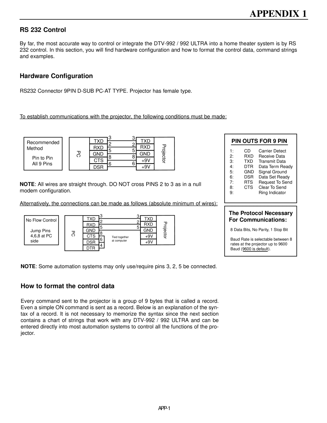
Rear Panel Terminology
Front Panel Terminology
Control panel terminology
Local Keypad
RCU control panel terminology
IR Transmission Indicator
AC Power mains Cord Connection
Power Check
Switching On/Off
Connections
Signal Input Connection to the Projector
Start up with full white image
Port No Projector Input Press Digit Button
Connecting a RGB Analog source with composite sync
Connecting a RGB Analog source with Tri-level sync
Rgbs or RGsB input selection
RGB3S or RG3sB input selection
Connecting a Component source
Connecting a Component source with Tri-level sync
YYB-YS or R-YYsB-Y input selection
Remote control
YYB-Y3S or R-YY3sB-Y input selection
Data communications
Battery installation in the RCU
Controlling
How to use your RCU
Using your RCU
How to display a projector address?
Hardware set up of the projector address
General Access Menu Items Source
Input selection
Analog Picture Controls
Pause key
Start UP of the Adjustment Mode
Adjustment mode
Start Up of the Adjustment Mode
Random Access Adjustment Mode
Starting up the random access adjustment mode
Overview ‘Random Access Adjustment’ mode
Selecting Setup Pattern
Internal Cross Hatch Pattern
Random access adjustment mode selection menu
Picture Tuning
Sync Fast/Slow Adjustment
Color Balance
Peaking
Color Select
Press Enter to display the color select menu
Display the projected image in that specific color
Focusing
Focusing
Geometry Adjustments
Horizontal Phase Adjustment
Phase
Geometry
Raster Shift Adjustment
Left-Right east-west Adjustments
Left Right E-W
Left Side Correction
Left Side Correction Left Keystone Left BOW
Top-Bottom north-south Adjustments
TOP Bottom N-S
Size Adjustment
Vertical Linearity Adjustment
Linearity
Blanking Adjustments
Blanking TOP Bottom Left Right
Convergence Adjustment
Coarse Convergence Adjustments
Convergence
Fine Convergence Adjustments
Vertical corners
Service Mode
Starting up the Service mode
Overview flowchart ‘Service’ mode
Identification
Copy a block
Identification
Copy a Block
Deletion of blocks
Deleting block by block
Delete a Block
Delete ALL Blocks
Change password
Change Language
Total Run Time
All settings to midposition
Undo all settings to midpos
Convergence mid
Undo R & B convergence mid
Dynamic Astigmatism spot shape adjustment
Arrow key Axial Astigmatism correction
G2 Adjustment
Common Settings 12C Diagnostics
CRT run in cycle
CRT RUN in Cycle Projector Warm UP
Projector warm up
Projector Warm UP
MESSAGES, WARNINGS, and Failures
Source
Failure
DTV-992
DTV-992 Ultra
Appendix
RS 232 Control
Sending a Record single instruction
Decimal values
STX
Sharpness
$02,$00,$00,$51,$0A,$00,$00,$00,$01,$5C
Quick Guide to using the EYE-QTMsystem
Overview
Easy-to-use, high precision automatic convergence system
Easy-to-use, high precision automatic geometry system
Compact, built-in system
Preparing your EYE-QTM
Access to EYE-QTMON-SCREEN Menus
EYE-QTMMENU
EYE-QTMSETUP
Setting the Configuration
Focusing the Camera Lens
Centering the Camera
Centering the Camera Horizontally
Centering the Camera Vertically
TOUCH-UP on Source ON/OFF
TOUCH-UP on Timer
Adjusting Other Sources
Reference Source
What is Being Measured by EYE-QTM
Learning a Reference
Adjusting Screen Size
On Current Source
TOUCH-UP
Align on Current Source
Align from Midposition on Current Source
On ALL Sources
TOUCH-UP on ALL Sources
Align on ALL Sources
Error Messages
Align from Midposition on ALL Sources
Interrupting the Automatic Convergence Process
No Pattern Error
Status Reporting Forced Break
Status Forced break
EYE-QTMDIAGNOSTICS
APX-16
Page
RUMA-003700 rev