( Continued from the previous page A. )
A
Yes
Defect or connection error
in the
( Continued from the previous page B. )
B
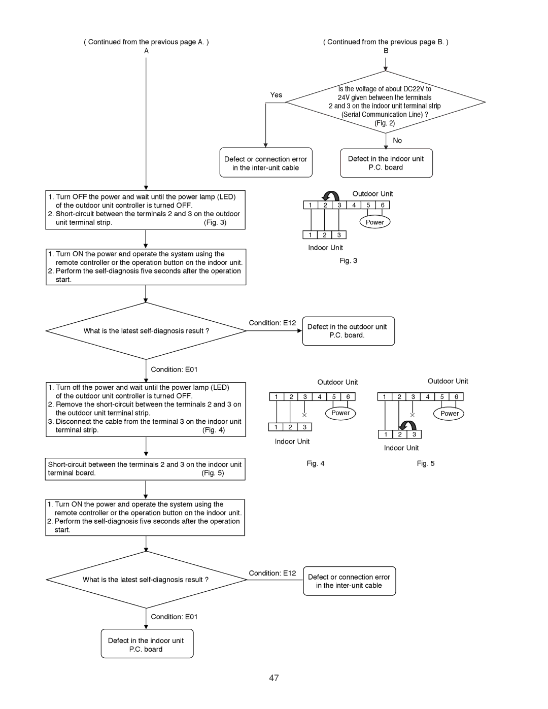
Is the voltage of about DC22V to 24V given between the terminals
2 and 3 on the indoor unit terminal strip
(Serial Communication Line) ?
(Fig. 2)
No
Defect in the indoor unit
P.C. board
1.Turn OFF the power and wait until the power lamp (LED) of the outdoor unit controller is turned OFF.
2.
unit terminal strip.(Fig. 3)
Outdoor Unit
1 | 2 | 3 | 4 | 5 | 6 |
Power
1 2 3
1.Turn ON the power and operate the system using the remote controller or the operation button on the indoor unit.
2.Perform the
What is the latest
Indoor Unit
Fig. 3
Condition: E12 | Defect in the outdoor unit |
| P.C. board. |
Condition: E01
1.Turn off the power and wait until the power lamp (LED) of the outdoor unit controller is turned OFF.
2.Remove the
3.Disconnect the cable from the terminal 3 on the indoor unit
terminal strip.(Fig. 4)
terminal board. | (Fig. 5) |
Outdoor Unit
1 2 3 4 5 6
![]() Power 1 2 3
Power 1 2 3
Indoor Unit
Fig. 4
Outdoor Unit
1 2 3 4 5 6
Power
1 2 3
Indoor Unit
Fig. 5
1.Turn ON the power and operate the system using the remote controller or the operation button on the indoor unit.
2.Perform the
What is the latest | Condition: E12 | Defect or connection error |
| ||
|
| in the |
Condition: E01
Defect in the indoor unit
P.C. board
47
