1-5. Additional Materials Required for Installation
1.Refrigeration (armored) tape
2.Insulated staples or clamps for connecting wire (See local codes)
3.Putty
4.Refrigeration lubricant
5.Clamps or saddles to secure refrigerant tubing
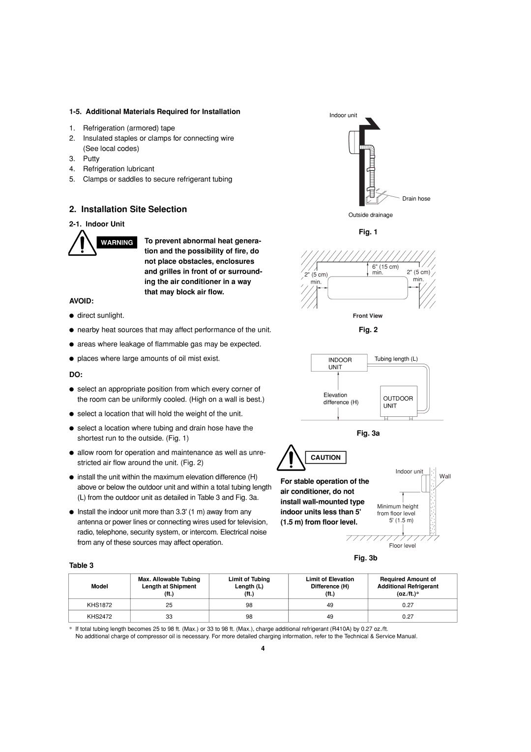
Indoor unit
![]() Drain hose
Drain hose
2. Installation Site Selection
Outside drainage
WARNING
AVOID:
●direct sunlight.
To prevent abnormal heat genera- tion and the possibility of fire, do not place obstacles, enclosures and grilles in front of or surround- ing the air conditioner in a way that may block air flow.
Fig. 1
| 6" (15 cm) | 2" (5 cm) |
2" (5 cm) | min. | |
| min. | |
min. |
| |
|
| |
| Front View |
|
●nearby heat sources that may affect performance of the unit.
●areas where leakage of flammable gas may be expected.
●places where large amounts of oil mist exist.
| Fig. 2 |
INDOOR | Tubing length (L) |
UNIT |
|
DO:
● select an appropriate position from which every corner of |
the room can be uniformly cooled. (High on a wall is best.) |
● select a location that will hold the weight of the unit. |
● select a location where tubing and drain hose have the |
shortest run to the outside. (Fig. 1) |
Elevation | OUTDOOR | |
difference (H) | ||
UNIT | ||
|
Fig. 3a
● allow room for operation and maintenance as well as unre- |
stricted air flow around the unit. (Fig. 2) |
● install the unit within the maximum elevation difference (H) |
above or below the outdoor unit and within a total tubing length |
(L) from the outdoor unit as detailed in Table 3 and Fig. 3a. |
● Install the indoor unit more than 3.3' (1 m) away from any |
antenna or power lines or connecting wires used for television, |
radio, telephone, security system, or intercom. Electrical noise |
from any of these sources may affect operation. |
CAUTION
For stable operation of the air conditioner, do not install
Indoor unit
Wall
Minimum height from floor level
5' (1.5 m)
Table 3
Floor level
Fig. 3b
| Max. Allowable Tubing | Limit of Tubing | Limit of Elevation | Required Amount of |
Model | Length at Shipment | Length (L) | Difference (H) | Additional Refrigerant |
| (ft.) | (ft.) | (ft.) | (oz./ft.)* |
|
|
|
|
|
KHS1872 | 25 | 98 | 49 | 0.27 |
|
|
|
|
|
KHS2472 | 33 | 98 | 49 | 0.27 |
|
|
|
|
|
*If total tubing length becomes 25 to 98 ft. (Max.) or 33 to 98 ft. (Max.), charge additional refrigerant (R410A) by 0.27 oz./ft.
No additional charge of compressor oil is necessary. For more detailed charging information, refer to the Technical & Service Manual.
4