Name and function of each part
[1] Name and function of each part
(Top View)
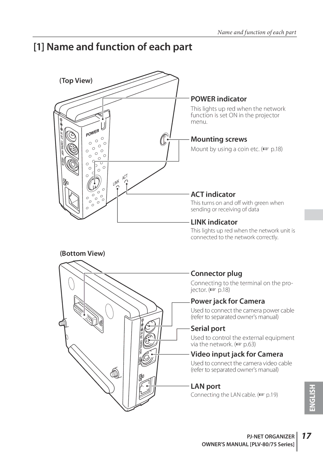
| POWER indicator |
|
| This lights up red when the network |
|
| function is set ON in the projector |
|
| menu. |
|
DC | Mounting screws |
|
CO |
| |
OU |
|
|
T |
|
|
NT | Mount by using a coin etc. (☞ p.18) |
|
O |
| |
RO |
|
|
L |
|
|
P |
|
|
RT |
|
|
V |
|
|
I |
|
|
D |
|
|
E |
|
|
O |
|
|
IN |
|
|
T |
|
|
AC |
|
|
LINK |
|
|
| ACT indicator |
|
| This turns on and off with green when |
|
| sending or receiving of data |
|
| LINK indicator |
|
| This lights up red when the network unit is |
|
| connected to the network correctly. |
|
(Bottom View) |
|
|
| Connector plug |
|
| Connecting to the terminal on the pro- |
|
| jector. (☞ p.18) |
|
| Power jack for Camera |
|
| Used to connect the camera power cable |
|
| (refer to separated owner's manual) |
|
D | Serial port |
|
|
| |
C | Used to control the external equipment |
|
OU |
| |
T |
|
|
CONT | via the network. (☞ p.63) |
|
RO |
| |
L |
|
|
PO | Video input jack for Camera |
|
R |
| |
T |
|
|
VI |
|
|
D |
|
|
E | Used to connect the camera video cable |
|
IN |
| |
O |
|
|
| (refer to separated owner's manual) |
|
| LAN port | ENGLISH |
| Connecting the LAN cable. (☞ p.19) | |
|
|
17
