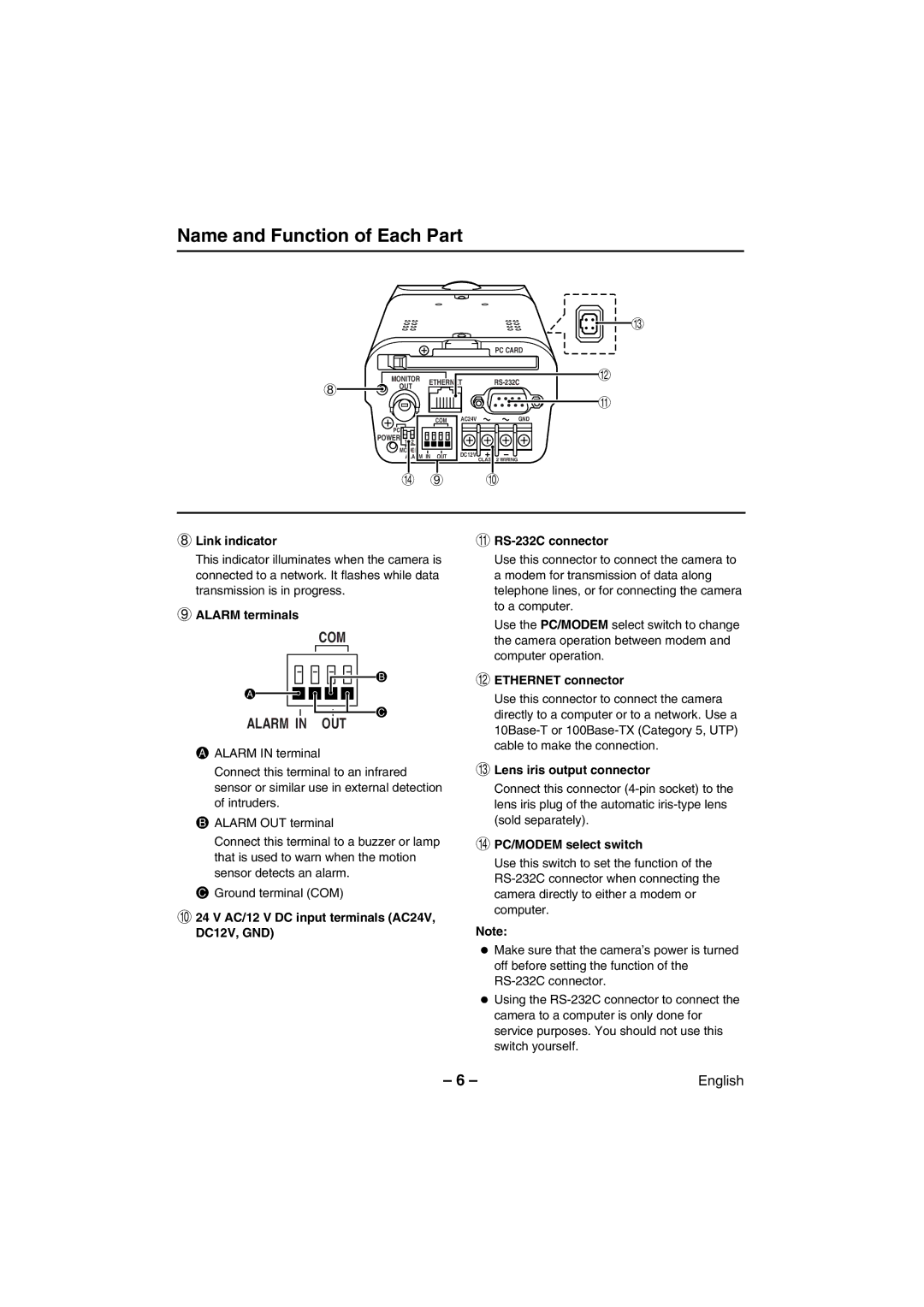
Name and Function of Each Part
I
|
|
| PC CARD |
| MONITOR | ETHERNET | H |
8 | OUT | ||
|
| ||
|
|
|
G
COM
PC![]()
![]()
POWER 1 | 2 |
MODEM
ALARM IN OUT
AC24VGND
DC12V
CLASS 2 WIRING
J 9 F
8Link indicator
This indicator illuminates when the camera is connected to a network. It flashes while data transmission is in progress.
9ALARM terminals
COM
B
A
C
ALARM IN OUT
AALARM IN terminal
Connect this terminal to an infrared sensor or similar use in external detection of intruders.
BALARM OUT terminal
Connect this terminal to a buzzer or lamp that is used to warn when the motion sensor detects an alarm.
CGround terminal (COM)
F24 V AC/12 V DC input terminals (AC24V, DC12V, GND)
G
Use this connector to connect the camera to a modem for transmission of data along telephone lines, or for connecting the camera to a computer.
Use the PC/MODEM select switch to change the camera operation between modem and computer operation.
HETHERNET connector
Use this connector to connect the camera directly to a computer or to a network. Use a
ILens iris output connector
Connect this connector
JPC/MODEM select switch
Use this switch to set the function of the
Note:
•Make sure that the camera’s power is turned off before setting the function of the
•Using the
– 6 – | English |