CT 400 and CT410 Desk Top Printers
Sato CL Series Printer PN 9001069A
CT Series Printer OPERATOR’S Manual
Appendices
Table of Contents
Programming
Interface Specifications
UPC-A/EAN-13
Section Printer Overview
Introduction
CT400 CT410
General Printer Specifications
Specification
Processing CPU
Character Fonts
Matrix Fonts
BAR Codes
UCC/EAN-128
Power Requirements
Physical
Optional Accessories
Accessory
This page left intentionally blank
Section Installation and Configuration
Unpacking
Setting UP the Printer
Installation and Configuration
Loading Ribbon CT4XXTT only
Ribbon Drive Spindles Ribbon Ass’y Latch
Loading Media
Roll Media
Roll Guide so that the Paper
Fanfold Media
Close and latch Print Head Assembly
Label Sensing
CT Series Printer Label Sensor Positioning
Operator Panel
Rear Connector Panel
Power
If Installed Fanfold Paper Slot
Parallel Interface
DSW1 DSW2 DSW3 Setting
Configuration Panel
Configuration Switch
Off Enable
DSW4 Setting
DSW5 Setting
DSW6 Setting
LED Error
Error Display
DSW8 Setting
Potentometer Adjustments
Mode Millimeters Inches Dots
Offset
Pitch Offset
Label Feed Direction Sensor Position
Print Darkness
HEX Dump Diagnostic Label
Print Test Labels
User Test Print
FACTORY/SERVICE Test Print
This page left intentionally blank
Darkness Print
Procedures
Adjusting the Print Quality
Supplies needed
Cleaning the Print HEAD, Platen and Rollers
Cleaning the Print Head
Cleaning the Platen and Paper Roller
Replacing the Print Head
Cleaning and Maintenance
Cleaning the Sensors
Supplies Needed Sato SA070 Cleaning Kit
This page left intentionally blank
Section Programming
Sato CT Programming Language
Control HEX Description Character Value
Using Basic
Protocol Control Codes
Open COM19600,E,8,1,CS,DS AS #1
Print Area
Print Area
Programming Reference
Rotated Fields
Command Default Settings
Command Codes
Sato CT Series Printers 9001069A
This page left intentionally blank
Bar Codes
MSI
Input to Printer
Esca
Printer Output
UCC-128
With Incrementing
Special Notes
Command Structure ESCBWaabbb
Command Function
Bar Codes, Expansion
ESCBW02100
Command Structure ESCBTabbccddee
Bar Codes, Variable Ratio
9001069A Sato CT Series Printers
ESCA3H+100V+0050
Command Structure ESCA3HabbbbVcdddd
Base Reference Point
Printer configuration until a new Base Reference Point
Command Structure Store Command ESCTabcc
Characters, Custom-Designed
ESCK1H903F
Printer Input
Character is affected by the following commands
Command Structure ESCLaabb
Character Expansion
This command will expand the following fonts
Command Structure
Character, Fixed Spacing
Character Pitch
This command is affected by the Escl Character Expansion
Character, Proportional Spacing
Escpr
Special Note
Command Structure ESC*a
Clear Print Jobs & Memory
Command Structure None
Continuous Forms Printing
ESCWDH0100V0050X0600Y0400
Command Structure ESCWDHaaaaVbbbbXccccYdddd
Copy Image Area
For the duplicate image
Command Structure ESCNULaaaa
Cut Job
Command Structure ESCCTaaaa
Cut
Cut Last
Command Structure Font XU
Fonts U, S, M, OA, OB, XU, XS & XM
Characters may be enlarged through the use of the Character
Command Structure ESCAESCRFaabbbb,nn...n
Font/Graphic Recall
Command Structure ESCAESCRDabb,ccc,ddd,nn. . .n
Font, Raster
Font, Vector
ESC$a,b,c,d
ESC$=data
ESC$A,100,200,0ESC$=123456
Pitch command can be used with Vector fonts
ESCWB1123456
Command Structure Font WB
Fonts WB, WL, XB & XL
Expansion rate is at least 3 times in each direction
Form Overlay, Recall
Form Overlay, Store
ESCGH006006
Command Structure ESCGabbbcccdata
Graphics, Custom
Custom graphic cannot be enlarged by the Escl Character
Job ID Store
Journal Print
Lines and Boxes
ESCFWaabcccc
ESCFWaabbVccccHdddd
ESCFW02H0200
Length
LINE/BOX
CT400 CT412
Escwksato
Command Structure ESCWKnnn. . . n
Job Name
Command Structure ESCYEa
Label/Tag Select
Line Feed
Sato CT Series Printers 9001069A
Command Structure ESCA1aaaabbbb
Media Size
Off-Line
ESCBP123456789
Command Structure ESCBPn...n
Postnet
Command Structure ESC#Eab
Print Darkness
Print Position
Bbbb
Command Structure ESCQaaaaaa
Print Quantity
Print Speed
ESCCS3
Repeat Label
Escc
Replace Data Partial Edit
9001069A Sato CT Series Printers
ESC100,50
Command Structure ESCaaaa,bbbb
Reverse Image
CT400 CL412
Command Structure ESC%a
Rotate, Fixed Base Reference Point
ESCF0001-001,04,03,0
Command Structure ESCFaaabcccc,dd,ee,f
Sequential Numbering
Value specified for Print Quantity should be equal to
Start/Stop Label
Two-Dimensional Symbols
Two-Dimensional Bar Codes Data Matrix, Data Format
Command Structure ESCBXaabbccddeeefffghh
ESCBX03080505000000001
Printer Outpu
ECC
Character SET Encoding Number Scheme
Two-Dimensional Bar Codes Data Matrix, Print Data
ESCDC00006000
Two-Dimensional Bar Codes Data Matrix, Sequential Numbering
Command Structure ESCFXaaabcccdddeee
9001069A Sato CT Series Printers
Example ESCBV1,2,3,123456789,222,333,MESSAGEESC
Two-Dimensional Bar Codes Maxicode
Command Structure ESCBVa,b,c,ddddddddd,eee,fff,gggg.....ESC
Mode Postal Code Country Code Service Class Message Length
Following modes are supported
Two-Dimensional Bar Codes
Command Structure ESCBKaabbcddeeffffnn...n
Command Function Printer Input
ESCBK0304400000021
9001069A Sato CT Series Printers
Printer Configuration Commands
Example ESCLD,,,%,#,&,*,~,0,0,D5
Command Structure ESCLD,a,b,c,d,e,f,g,h,i,j
Eurocharacter Select
Command HEX Description Parameter Value
Printer Setting
Command Structure ESCPGabcdefghhijklmnopqrstuvwxyz
Placement Separate data stream sent to printer Default None
All command parameter values must be in Ascii format
Print Mode
Command Structure ESCPMa
Command Structure ESCPHa
Print Type
Command Structure ESCPOabcc
Pitch Offset
Command Structure ESCIGa
Sensor Type
Command Structure ESCI2abcde
Serial Interface Parameters
Section Interface Specifications
Interface Types
Multi Job Buffer
Receive Buffer
Single Job Buffer
Data Streams
Electrical Specifications
Ieee 1284 Parallel Interface
PIN Signal Direction
Ieee 1284 Parallel Interface Pin Assignments
PIN Assignments
General Specifications
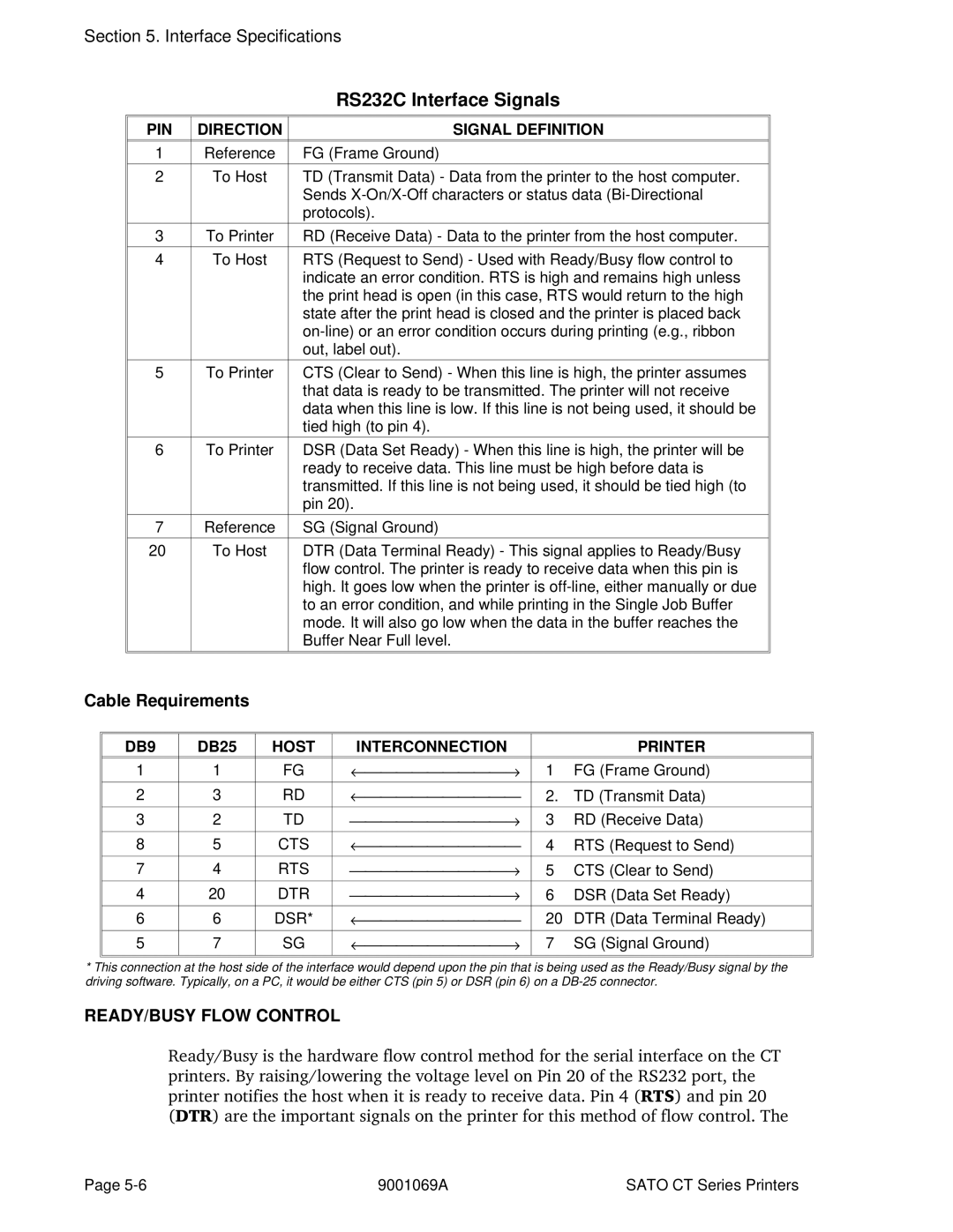
Optional RS232C Serial Interface
PIN Direction Signal Definition
Cable Requirements
READY/BUSY Flow Control
DB9
Data Streams
Universal Serial BUS USB Optional Interface
On/X-Off Flow Control
Local Area Network LAN Optionalinterface
BI-DIRECTIONAL Communications
ENQUIRE/ACK/NAK
Enquire ENQ
Cancel can
Print Job
Print Stop DLE
Print Start DC1
Status Byte Definition, Bi-Com Protocol
Byte HEX Description Number Value
Status Response
Printer Status SOH + MG
Label Media
Byte Value Description Number
Counter Status SOH + ME
Sensor Status SOH + SG
Head Status SOH + HC
System Version Information
Memory Status
Byte Value Description Number Ascii
Form Overlay Status SOH + FO
Font Configuration SOH + FG
Serial Interface Settings
Interface Status
Initial Checklist
Using the Ieee 1284 Parallel Interface
Troubleshooting
Using the RS232C Serial Interface
Error Signals
Vcdddd
A1aaaabbbb
A3Habbbb
Babbcccd
BDabbcccd
BKaabbcdd Eeefffnn...n,g
BPn...n
BTabbccddee
BVa,b,c
Ddddddddd
Eee,f f f,gg..g
CSa
CTaaaa
Dabbcccd
DCxx...x
FWaabbVccc
Hdddd
FWccVddd
FXaaabccc
IGa
I2abcde
Laabb
LDa,b,c,d,e,f,g,i
Paa
PGa.....z
PMa
PHa
RDabb,ccc,ddd
Nn . . . n
RFaabbbb,nn..n
Vbbbb
WLa
XLa
XBa
YEa
$a,b,c,d
$=data Data for Vector font #Eab
Aaaa,bbbb
Zero
NULaaaa
~aaaa
A-12 9001069A Sato CT Series Printers
Appendix B BAR Code Specifications
BAR Code Symbologies
Codabar
ESCB0bbcccd data d Ratio ESCBD0bbcccd data d
ESCD0bbcccd data d
Character Set
Command Structure Ratio ESCB1bbccc* data
Code
ESCBD1bbccc* data
ESCD1bbccc* data
Interleaved Two of Five I 2/5
ESCBD2bbccc data
ESCD2bbccc data
Density Model
Narrow Bar
Width mils Factor
ODD Even
Calculating
Mod 10 Check Digit
Command Structure ESCB4bbccc data
ESCD4bbccc data
Industrial Two of Five
B5bbccc data
BD5bbccc data
D5bbccc data
Matrix Two of Five
ESCB6bbccc data
ESCBD6bbccc data
ESCD6bbccc data
Command Structure ESCBGbbcccdd data
Density Char/inch Model Dimension Mils Subsets a Subset C
ESCDAbbccc data d
ESCBAbbccc data d
ESCBDAbbccc data d
Density Model Dimension Char/inch Ratio Mils
Command Structure ESCBEbbccc data
ESCDEbbccc data
Command Structure ESCBFbbccc data
Bookland UPC/EAN Supplements
Command Structure ESCBIbbcccd data
UCC-128
B-16 9001069A Sato Ct Series Printers
Command Structure Escbp data
Command Structure Data Format
Data Matrix
Sequential Numbering ESCFXaaabcccdddeee
Print Data
Structure of this symbology
Mode Postal Code Country Code Service Ctass Message Length
Command Structure ESCBFaabbcddeeffffnnn...n
Code 128 Character Table
Value Subset a Subset B Subset C
Code 128 Character Table
Code 128 Character Table cont’d
Appendix C Custom Characters and Graphics
CUSTOM-DESIGNED Character Example
Appendix C Custom Characters and Graphics
Sato CT Series Printers 9001069A C-3
Custom Graphics Example
Sato CT Series Printers 9001069A C-5
C-6 9001069A Sato CT Series Printers
Sato CT Series Printers 9001069A C-7
C-8 9001069A Sato CT Series Printers