Sato Europe GmbH
Copyright 1999 Sato Europe GmbH
Contents
Memory Card Function
MSI
EAN-8
UPC-E
188
Introduction
Sato Risc Programming Language
Selecting Protocol Control Codes
Using Basic
Control Standard Non Description Character DSW2-7
Printing with the Parallel Port
Lprint E$A
Printing with the RS232 Port
Print Area
OEM right-hand Desktop printer
Print Area for CL Printers CL 608 VA CL 612 VA
Escax
Introduction
Print Area for S-Type Printers M8485S M4890S M8460S M8459S
Print Area for XL and RV printers XL410 M8400RV
First Method Using Base Reference Point
Second Method Using Horizontal Offset Position
CL612 Label
Example for first Method, using base reference point
Example for second Method, horizontal position offset
95mm70mm 165mm Label feed direction
This page is intentionally left blank
Command Codes
Bar Codes
Programming Manual Command Codes
Carriage Returns and Line Feeds have been added to
UCC-128 without Incrementing Input
Command Codes Programming Manual
Bar Codes, Expansion
ESCBWaabbb
Bar Codes, Variable Ratio
ESCBTabbccddee
Programming Manual Command Codes
Base Reference Point
ESCA3H-aaaaVbbbb
CL 608 VA CL 612 VA
M8485S M8490S M8460S M8459S
ESCKab90cc
Characters, Custom-Designed
ESCT1H3F
ESCT1H3F
Character Expansion
Programming Manual Command Codes
Character, Fixed Spacing
ESC PR
Character Pitch
Command Codes Programming Manual
Escpr
Character, Proportional Spacing
Escps
Clear Print Jobs & Memory
Continuous Forms Printing
Copy Image Area
ESCWDHaaaaVbbbbXccccYdddd
Horizontal Aaaa Vertical 0001 to Bbbb
Cutter Command
Fonts U, S, M, OA, OB, XU, XS & XM
Output
Font, Vector
Ascenders Äg 64 % Descenders
Fonts WB, WL, XB & XL
Input
Form Feed
Form Overlay, Recall
Form Overlay, Store
ESCGabbbcccdata
Graphics, Custom
Data
Programming Manual Command Codes
Graphics, PCX
ESCGPaaaaa,data
Job ID Store
Journal Print
ESC J
Lines and Boxes
Box ESCFWaabbVccccHdddd
Command Codes Programming Manual
Line Feed
Command Codes Programming Manual
Mirror Image
ESCRMaaaa, bbbb
Max Print Direction
Escrm ESCQ1ESCZ
Normal Direction
Mirror Image with Rotation
Specifying of a mirror command between print fields
Mirror Image with specifying area
Case of specifying mirror command after the last print field
% specifying effects on RM command and print fields
Output Mirror position
ESC@,nn...n Nn...n
Off-Line/Pause
Escz
Postnet
ESCBPn...n
Print Darkness
Print Length, Expanded
Escar
Print Position
Programming Manual Command Codes
Print Quantity
ESCQaaaaaa
ESCCS6
Print Speed
Printer Speed
M8459S
Repeat Label
Escc
Replace Data Partial Edit
Programming Manual Command Codes
Reverse Image
ESCaaaa,bbbb
CL 608 VA CL 612 VA
Rotate, Fixed Base Reference Point
Programming Manual Command Codes
Rotate, Moving Base Reference Point
Output
Sequential Numbering
ESCFaaaabcccc,dd,ee
Escz
Start/Stop Label
Calendar Option Commands
Calendar Increment
ESCWPabbb
Programming Manual Command Codes
Calendar Print
= from firmware version 1E2050, 1E3002 for CL6xxVA
Output
Calendar Set
ESCWTaabbccddee
Memory Card Option Commands
These commands require the Memory Card Option
Memory Card Function Clear Card Memory
Memory Card Function Expand Memory Area
Memory Card Function Fonts, TrueType Recall
ESCBJRabbccddeeeeff...f
Download ESCBJDcccccddddee...e
Memory Card Function Fonts, TrueType Store
Escbj
Memory Card Function Format/Field Recall
ESCYR,aa ESC/D,bb,cc...c
Memory Card Function Format/Field Store
ESCYS,aaESC/N,bb,cc
106
Memory Card Function Graphics, Custom Recall
108
Memory Card Function Graphics, Custom Store
ESCGIabbbcccddddata
110
Memory Card Function Graphics, PCX Recall
Memory Card Function Graphics, PCX Store
ESCPIaaa,bbbbb,data
Data Data
Close #2
Memory Card Function Initialize
ESCBJFaaaaaaaa
Memory Card Function Slot Select
ESCCC1
Status
Escbjs
116
Custom Protocol Command Codes Download
ESCLD,a,b,c,d,e,f,g,h,i
118
Instruction
Start Code. Begins all print jobs
Dabbcccd
BKaabbcdd Eeefffnn...n
BPn...n
BTabbccddee
BVaaa,bbb Cccccc,dddd Ee...e
CSa
DCxx...x
Eaaa
Faaaabcccc Ddee
FXaaabccc
Gabbbccc Data
GPaaaaa
Haaaa
LD,a,b,c,d G,i Download Protocol Command Codes. Downloads a
Laabb
Paa
Qaaaaaa
Rotate, Moving Base Reference Point. Rotates
Tabccdata Store Custom Designed Characters. To create
WBa
WDHaaaaVbbbb
XBa
XLa
XWa
Rotate Fixed Base Reference Point . Rotates prin
$=data Data for Vector font #Ea
Aaaa,bbbb
Zero Replace Data Partial Edit. Provides the ability to
Clear Print Jobs and Memory. Clears individual
~aaaa Cutter Command. Controls the cutting of labels when
Used in place of the ~
JJJ
Calendar Option Commands
WPabbb
Memory Card Option Commands
GIabbbcccdd Ee...e
GRcc
PIaa,bbbbb Cc...c
PYaa Recall PCX Graphics File. Recalls a PCX graphics
132
Bar Code Specifications
UPC-A/EAN-13 EAN-8
Codabar
Code
Interleaved Two of Five I 2/5
ESCB2bbccc data
ESCBD2bbccc data
ESCD2bbccc data
UPC-A/EAN-13
ESCB3bbccc data ESCD3bbccc data ESCBD3bbccc data
Bar Code Specifications Programming Manual
Printer
EAN-8
ESCB4bbccc data ESCD4bbccc data
Industrial Two of Five
Ratio B5bbccc data Ratio BD5bbccc data Ratio D5bbccc data
Matrix Two of Five
ESCB6bbccc data
ESCBD6bbccc data
ESCD6bbccc data
ESCBGbbcccdd data
Sato Risc Printers 143
144
ESCBDAbbccc data d
ESCBAbbccc data d
ESCDAbbccc data d
RatioESCBCbbcccdd data
A-Z, -, ., Space, $, /, +, %
UPC-E
ESCBEbbccc data ESCDEbbccc data
Bookland UPC/EAN Supplements
ESCBFbbccc data
UCC-128
ESCBIbbcccd data
150
Escbp data Data
Two-Dimensional Bar Codes Data Matrix, Data Format
ESCBXaabbccddeeefffghh
Bit CRC
Number
Ascii
Two-Dimensional Bar Codes Data Matrix, Print Data
ESCDCxx...x
Two-Dimensional Bar Codes Data Matrix, Sequential Numbering
ESCFXaaabcccdddeee
156
Two-Dimensional Bar Codes Maxicode Vers
ESCBVa,b,c,ddddddddd,eee,fff,DDD
Ddd..d
DDD Data Message Do not enter Null Code
Two-Dimensional Bar Codes
ESCBKaabbcddeeffffnn...n
Sato Risc Printers 159
Two-Dimensional Bar Codes QR Code Optional Special Firmware
ESC2D30, a,bb,c,d ee, ff, gg
Escds k, nn...n
Nn...n Data Escdn IIII, nn...n
Sato Risc Printers 161
162
Sato Risc Printers 163
164
Sato Risc Printers 165
166
Sato Risc Printers 167
168
Overview
Interface Types
Receive Buffer
Multi Job Buffer
RS232C Serial Interface
Asynchronous Ascii
Data Transmission Rate
Character Format
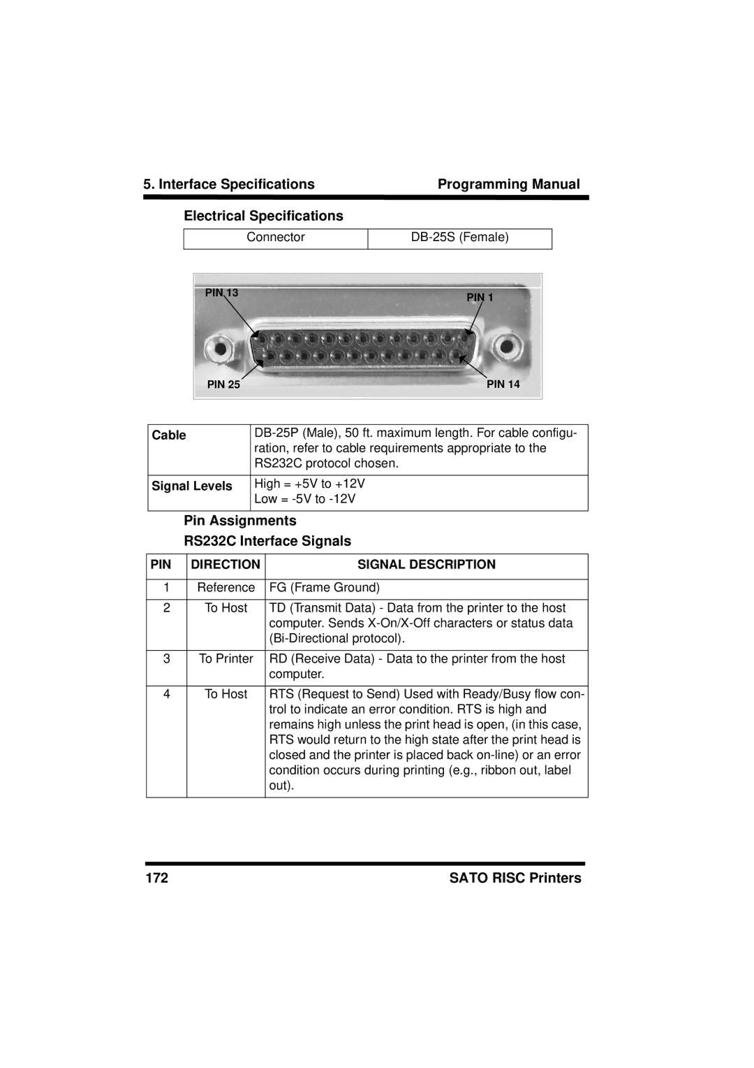
Signal Levels
Cable
Sato Risc Printers 173
Cable Requirements
Stxesca . . Job#1 . . Esczetxstxesca . . Job#n . . Esczetx
Sato Risc Printers 175
Status Response
STX 2 Byte ID1 Status Byte6 Byte Label RemainingETX
Sato Risc Printers 177
178
Printer Connector
Cable Connector
Signal Level
Centronics Parallel Interface
Connector
Data Streams
Standard Operation
Repeat Print
Error Signals
184
Sato Risc Printers 185
186
Troubleshooting
Initial Checklist
Troubleshooting the Centronics Parallel Interface
ESCA-DATA---ESCZ
Troubleshooting the RS232C Serial Interface
Error Signals M8400RV and M84S Series Printers
Error
Eeprom
Parity
Error Signals CL408/412
Error Signals CL608/612 VA
Parity Error
Error Signals XL400/410
Beep Error Condition To Clear
Sato Risc Printers 195
196
Custom Protocol Command Codes
Description
STX ETX ESC ENQ Can Offline
Download Command Structure
Online
Download Procedure
User Download
Lprint E$ LD,,,,@,!,~,,0,0
Custom Characters And Graphics
Custom-designed Character Example
202
Sato Risc Printers 203
204
Binary
Hex
Sato Risc Printers 207
208
Sato Risc Printers 209
210
PCX Graphics Example
212