IL•1F CANopen DS301 | 3 Basics |
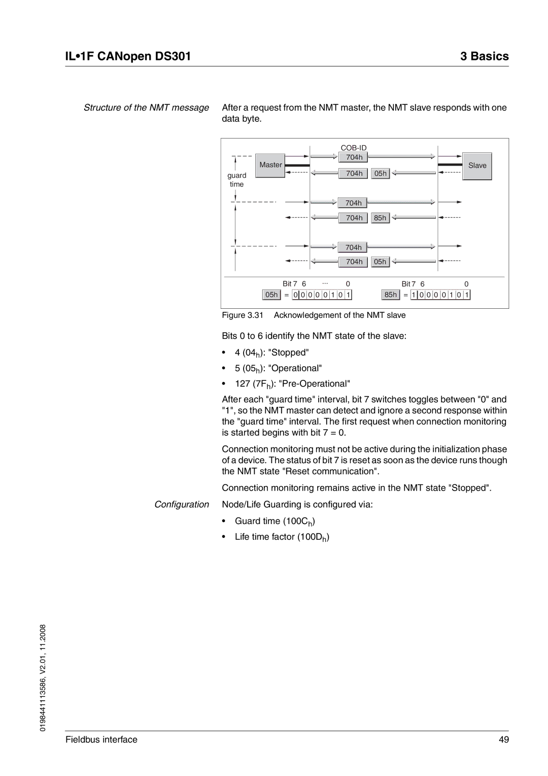
Structure of the NMT message After a request from the NMT master, the NMT slave responds with one data byte.
|
|
|
|
| ||
Master |
|
| 704h |
|
| Slave |
|
| 704h | 05h |
| ||
guard |
|
|
|
| ||
time |
|
|
|
|
|
|
|
|
| 704h |
|
|
|
|
|
| 704h | 85h |
|
|
|
|
| 704h |
|
|
|
|
|
| 704h | 05h |
|
|
| Bit 7 6 | ... | 0 |
| Bit 7 6 | 0 |
|
|
| ||||
05h | = 0 0 0 0 0 1 0 1 | 85h | = 1 0 0 0 0 1 0 1 | |||
Figure 3.31 Acknowledgement of the NMT slave
Bits 0 to 6 identify the NMT state of the slave:
•4 (04h): "Stopped"
•5 (05h): "Operational"
•127 (7Fh):
After each "guard time" interval, bit 7 switches toggles between "0" and "1", so the NMT master can detect and ignore a second response within the "guard time" interval. The first request when connection monitoring is started begins with bit 7 = 0.
Connection monitoring must not be active during the initialization phase of a device. The status of bit 7 is reset as soon as the device runs though the NMT state "Reset communication".
Connection monitoring remains active in the NMT state "Stopped".
Configuration Node/Life Guarding is configured via:
•Guard time (100Ch)
•Life time factor (100Dh)
0198441113586, V2.01, 11.2008
Fieldbus interface | 49 |