3 Basics | IL•1F CANopen DS301 |
Operating mode modeStat This field corresponds to bits 0 ... 2 of the object Status.xMode_act.
|
| Bits 6 and 7 provide additional information that can be used for synchro- |
|
| nized operating mode control via the PDOs. |
|
| The field contains the following information: |
|
|
|
Bit | Name | Description |
|
|
|
0...2 | mode | currently set operating mode as in R_PDO4 |
|
|
|
5 | ref_ok | Is set if homing of the product by means of a reference movement or position setting was |
|
| successful. |
|
|
|
6 | ME, ModeError | Set if a request of the master via R_PDO4 data was rejected by the product. |
|
|
|
7 | MT, ModeToggle | Mirrors bit 7 (Mode Toggle) of R_PDO4 |
|
|
|
3.4.2.4Handshake with Mode Toggle Bit
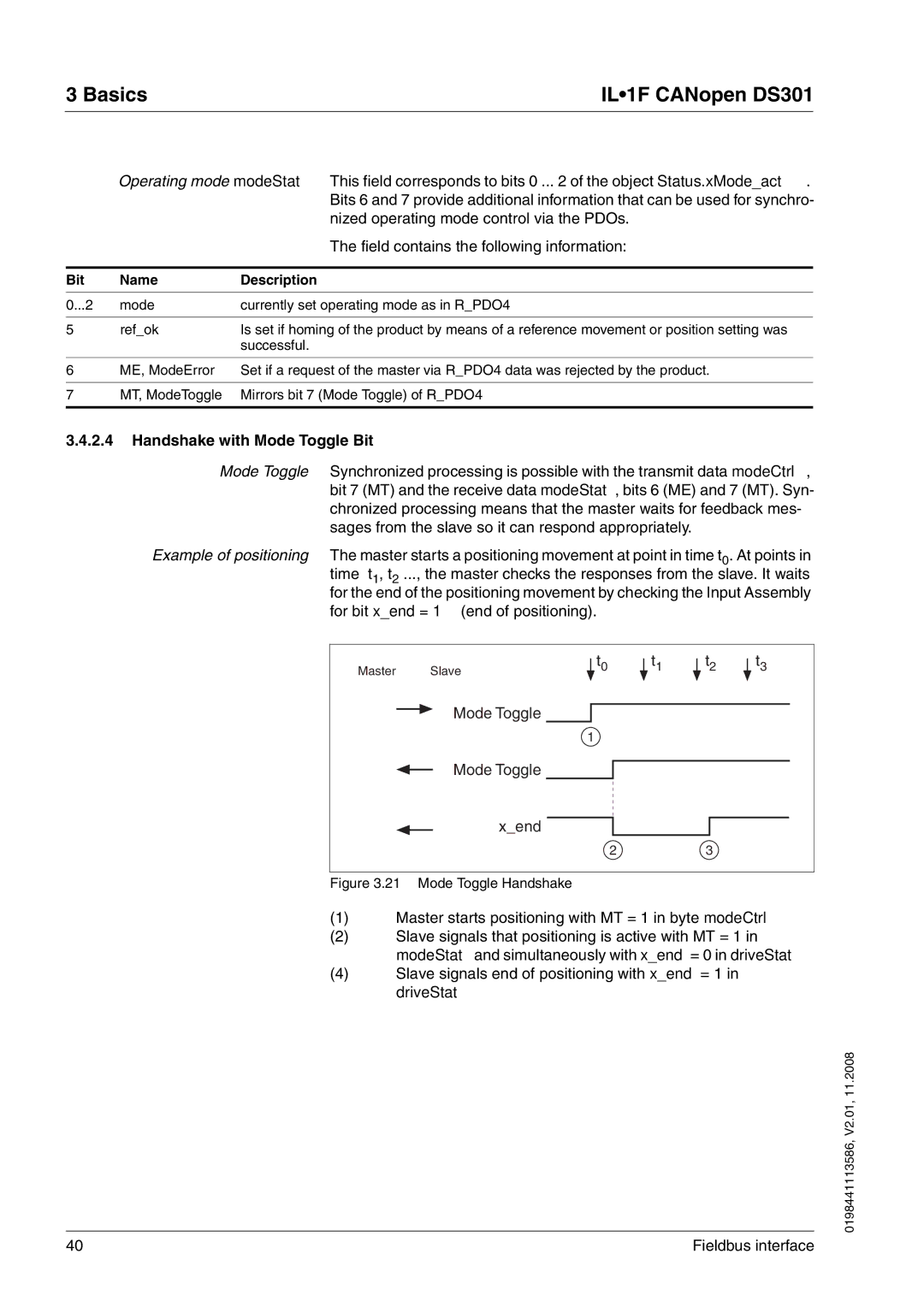
Mode Toggle Synchronized processing is possible with the transmit data modeCtrl, bit 7 (MT) and the receive data modeStat, bits 6 (ME) and 7 (MT). Syn- chronized processing means that the master waits for feedback mes- sages from the slave so it can respond appropriately.
Example of positioning The master starts a positioning movement at point in time t0. At points in time t1, t2 ..., the master checks the responses from the slave. It waits for the end of the positioning movement by checking the Input Assembly for bit x_end = 1 (end of positioning).
Master | Slave |
| t0 |
| |||
|
|
Mode Toggle
1
t1
t2
t3
Mode Toggle
x_end
23
Figure 3.21 Mode Toggle Handshake
(1)Master starts positioning with MT = 1 in byte modeCtrl
(2)Slave signals that positioning is active with MT = 1 in
modeStat and simultaneously with x_end = 0 in driveStat
(4)Slave signals end of positioning with x_end = 1 in driveStat
0198441113586, V2.01, 11.2008
40 | Fieldbus interface |
