5. SYSTEM PARAMETERS | English |
Parameter
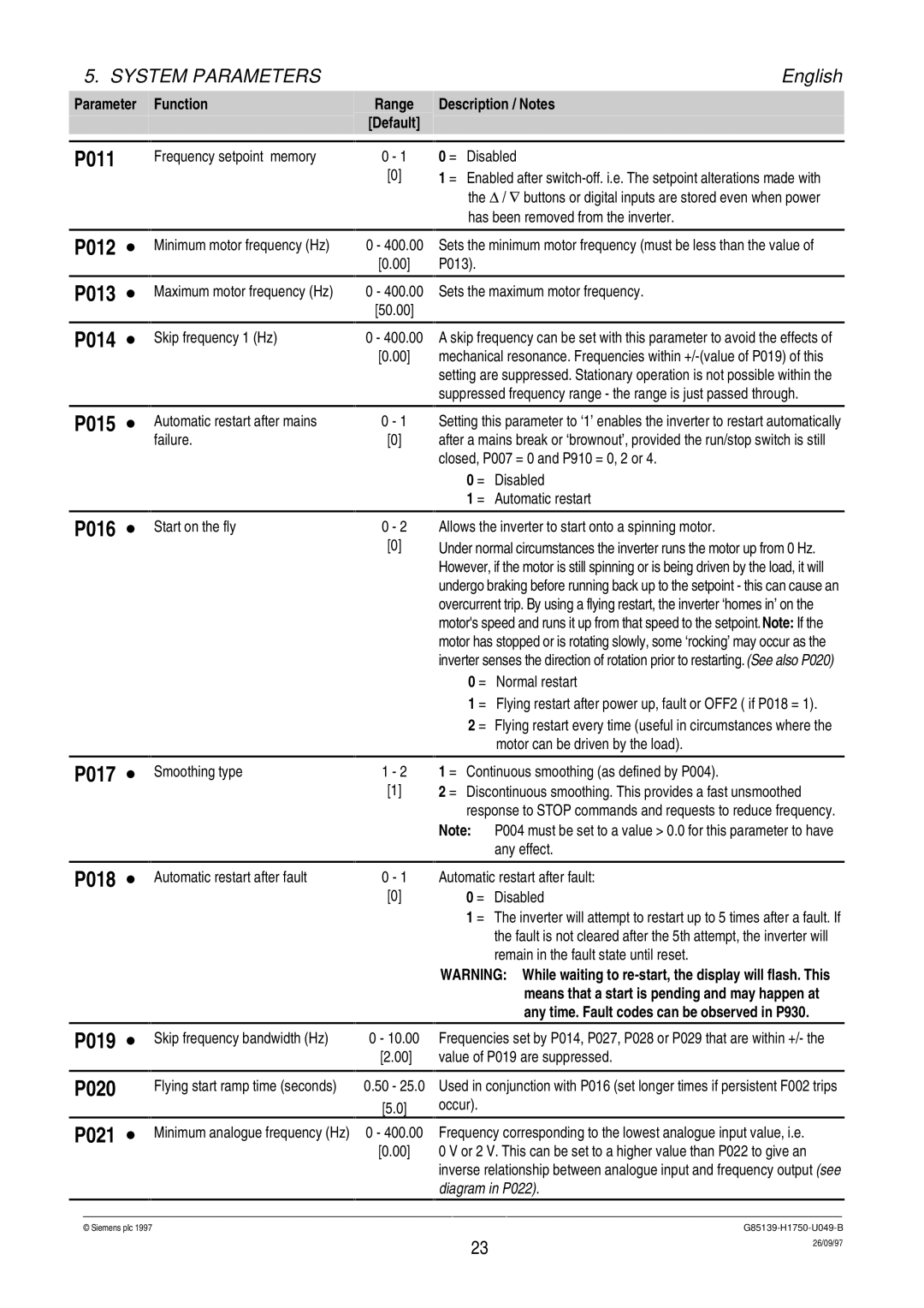
P011
| Function |
| Range |
|
|
| [Default] |
|
| ||
|
|
|
|
| Frequency setpoint memory | 0 - 1 | |
|
| [0] | |
Description / Notes
0 = Disabled
1 = Enabled after
P012 ∙
P013 ∙
P014 ∙
P015 ∙
Minimum motor frequency (Hz) | 0 - 400.00 |
| Sets the minimum motor frequency (must be less than the value of | ||
| [0.00] |
| P013). |
| |
|
|
|
|
| |
Maximum motor frequency (Hz) | 0 - 400.00 |
| Sets the maximum motor frequency. | ||
| [50.00] |
|
|
| |
|
|
|
|
| |
Skip frequency 1 (Hz) | 0 - 400.00 |
| A skip frequency can be set with this parameter to avoid the effects of | ||
| [0.00] |
| mechanical resonance. Frequencies within | ||
|
|
|
| setting are suppressed. Stationary operation is not possible within the | |
|
|
|
| suppressed frequency range - the range is just passed through. | |
|
|
|
|
| |
Automatic restart after mains | 0 - 1 |
| Setting this parameter to ‘1’ enables the inverter to restart automatically | ||
failure. | [0] |
| after a mains break or ‘brownout’, provided the run/stop switch is still | ||
|
|
|
| closed, P007 = 0 and P910 = 0, 2 or 4. | |
|
|
| 0 = | Disabled | |
|
|
| 1 = | Automatic restart | |
P016 ∙
Start on the fly | 0 - 2 |
| [0] |
Allows the inverter to start onto a spinning motor.
Under normal circumstances the inverter runs the motor up from 0 Hz. However, if the motor is still spinning or is being driven by the load, it will undergo braking before running back up to the setpoint - this can cause an overcurrent trip. By using a flying restart, the inverter ‘homes in’ on the motor's speed and runs it up from that speed to the setpoint.Note: If the motor has stopped or is rotating slowly, some ‘rocking’ may occur as the inverter senses the direction of rotation prior to restarting.(See also P020)
0 = Normal restart
1 = Flying restart after power up, fault or OFF2 ( if P018 = 1).
2 = Flying restart every time (useful in circumstances where the motor can be driven by the load).
P017 ∙
P018 ∙
Smoothing type | 1 - 2 | 1 = | Continuous smoothing (as defined by P004). |
| [1] | 2 = | Discontinuous smoothing. This provides a fast unsmoothed |
|
|
| response to STOP commands and requests to reduce frequency. |
Note: P004 must be set to a value > 0.0 for this parameter to have any effect.
Automatic restart after fault | 0 - 1 | Automatic restart after fault: | |
| [0] | 0 = | Disabled |
|
| 1 = | The inverter will attempt to restart up to 5 times after a fault. If |
|
|
| the fault is not cleared after the 5th attempt, the inverter will |
|
|
| remain in the fault state until reset. |
WARNING: While waiting to
P019 ∙
P020
P021 ∙
Skip frequency bandwidth (Hz) | 0 - 10.00 |
| Frequencies set by P014, P027, P028 or P029 that are within +/- the | |
| [2.00] |
| value of P019 are suppressed. | |
|
|
|
|
|
Flying start ramp time (seconds) | 0.50 - 25.0 |
| Used in conjunction with P016 (set longer times if persistent F002 trips | |
|
| [5.0] |
| occur). |
Minimum analogue frequency (Hz) | 0 - 400.00 |
| Frequency corresponding to the lowest analogue input value, i.e. | |
| [0.00] |
| 0 V or 2 V. This can be set to a higher value than P022 to give an | |
|
|
|
| inverse relationship between analogue input and frequency output (see |
|
|
|
| diagram in P022). |
© Siemens plc 1997G85139-H1750-U049-B
23 | 26/09/97 |
|