2. INSTALLATION | English |
2.3.3 Power and Motor Connections - Frame Size C
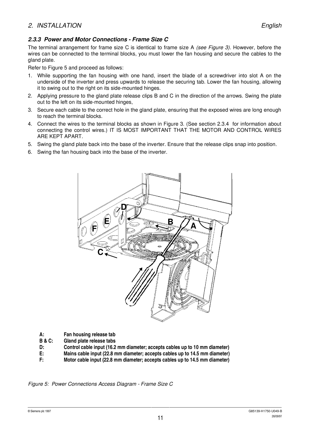
The terminal arrangement for frame size C is identical to frame size A (see Figure 3). However, before the wires can be connected to the terminal blocks, you must lower the fan housing and secure the cables to the gland plate.
Refer to Figure 5 and proceed as follows:
1.While supporting the fan housing with one hand, insert the blade of a screwdriver into slot A on the underside of the inverter and press upwards to release the securing tab. Lower the fan housing, allowing it to swing out to the right on its
2.Applying pressure to the gland plate release clips B and C in the direction of the arrows. Swing the plate out to the left on its
3.Secure each cable to the correct hole in the gland plate, ensuring that the exposed wires are long enough to reach the terminal blocks.
4.Connect the wires to the terminal blocks as shown in Figure 3. (See section 2.3.4 for information about connecting the control wires.) IT IS MOST IMPORTANT THAT THE MOTOR AND CONTROL WIRES ARE KEPT APART.
5.Swing the gland plate back into the base of the inverter. Ensure that the release clips snap into position.
6.Swing the fan housing back into the base of the inverter.
D
E ![]() B
B
F![]() A
A
C ![]()
A:Fan housing release tab
B & C: Gland plate release tabs
D:Control cable input (16.2 mm diameter; accepts cables up to 10 mm diameter)
E:Mains cable input (22.8 mm diameter; accepts cables up to 14.5 mm diameter)
F:Motor cable input (22.8 mm diameter; accepts cables up to 14.5 mm diameter)
Figure 5: Power Connections Access Diagram - Frame Size C
© Siemens plc 1997G85139-H1750-U049-B
11 | 26/09/97 |
|