English | 2. INSTALLATION |
2.2 Mechanical Installation
WARNING
THIS EQUIPMENT MUST BE EARTHED.
To guarantee the safe operation of the equipment it must be installed and commissioned properly by qualified personnel in compliance with the warnings laid down in these operating instructions.
Take particular note of the general and regional installation and safety regulations regarding work on dangerous voltage installations (e.g. VDE), as well as the relevant regulations regarding the correct use of tools and personal protective gear.
The mains input and motor terminals can carry dangerous voltages even if the inverter is inoperative. Use insulated screwdrivers only on these terminal blocks.
Environmental Requirements
Hazard
Temperature
Altitude
Shock
Vibration
Atmospheric
Pollution
Water
Overheating
Notes
Min. = 0°C
Max. = 50°C
If the Inverter is to be installed at an altitude > 1000 m, derating will be required.(Refer to DA 64 Catalogue).
Do not drop the inverter or expose to sudden shock.
Do not install the inverter in an area where it is likely to be exposed to constant vibration.
Do not install the inverter near sources of
Do not install the inverter in an environment which contains atmospheric pollutants such as dust, corrosive gases, etc.
Take care to site the inverter away from potential water hazards. e.g. Do not install the inverter beneath pipes that are subject to condensation.
Ensure that the inverter’s air vents are not obstructed.
Make sure that there is an adequate
1.Using the formula below, calculate the airflow
required.
2.Install cabinet cooling fan(s) if necessary,
Note:
Typical dissipation (Watts) = 3% of inverter rating.
ΔT = Allowable temperature rise within cabinet in °C.
3.1 = Specific heat of air at sea level.
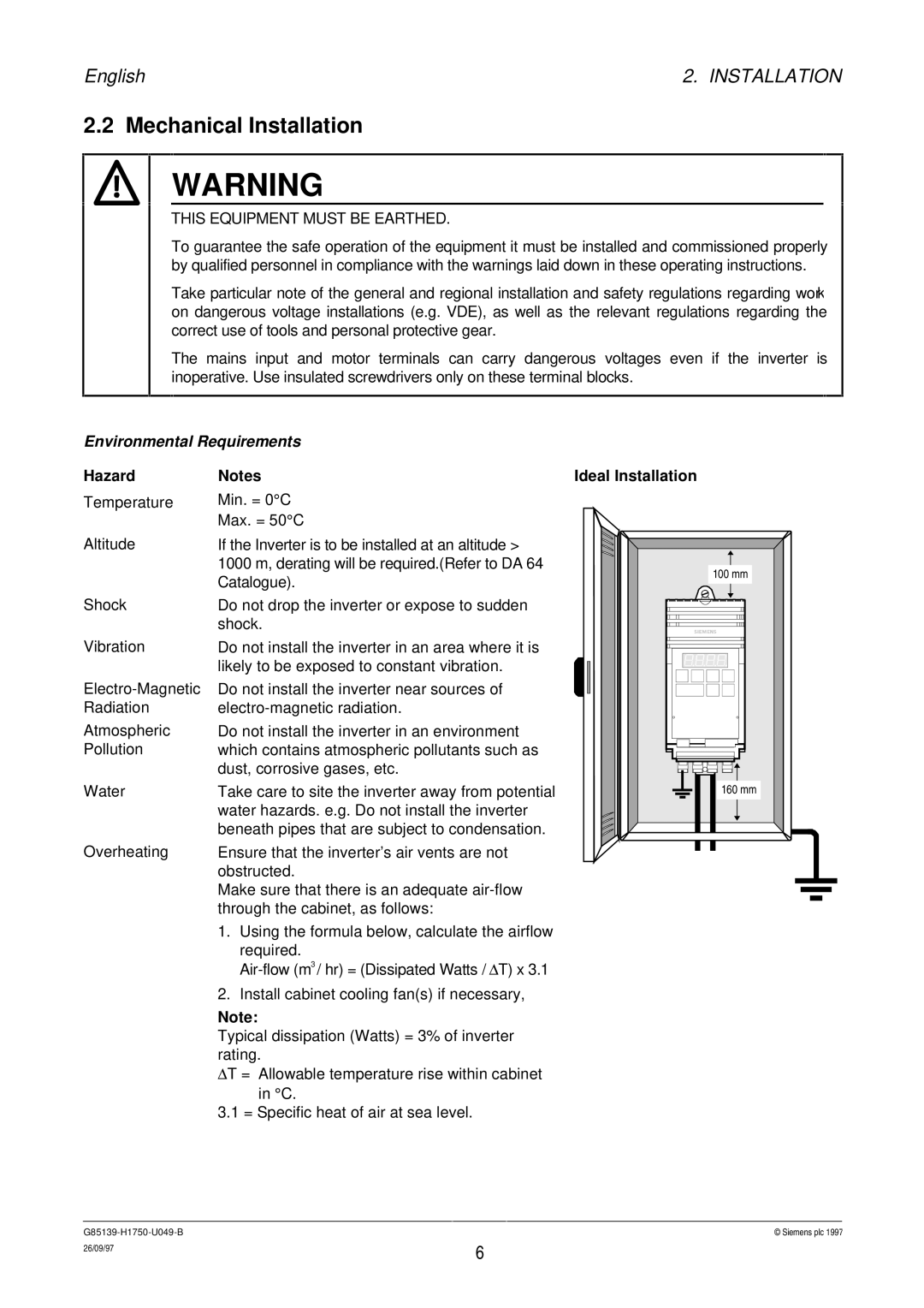
Ideal Installation
100 mm |
160 mm |
© Siemens plc 1997 | |
26/09/97 | 6 |
|