English |
|
|
|
|
| 5. SYSTEM PARAMETERS |
Parameter |
| Function |
| Range |
| Description / Notes |
|
|
|
| [Default] |
|
|
|
|
|
|
| ||
|
|
|
|
|
|
|
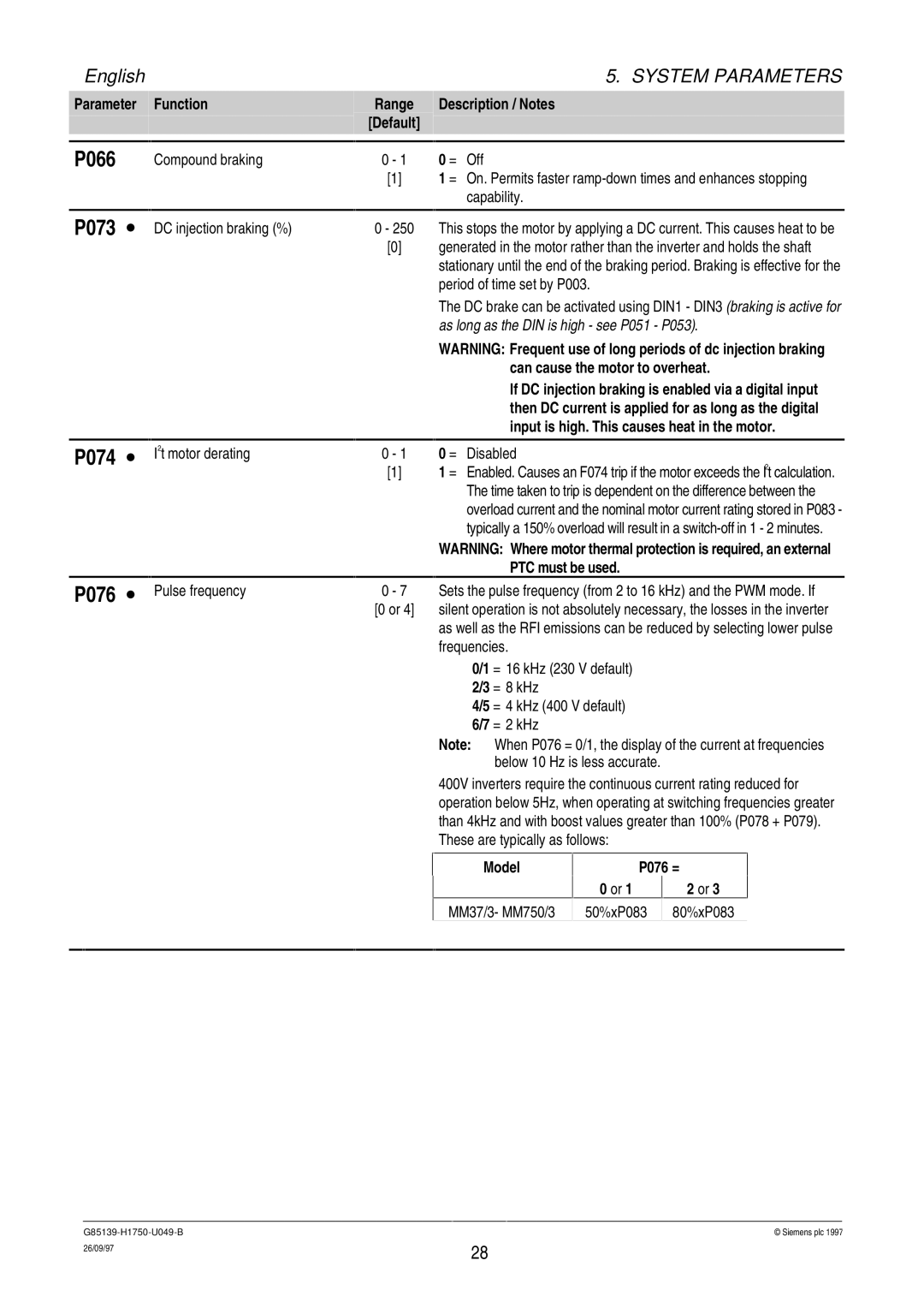
P066 |
| Compound braking | 0 - 1 |
| 0 = Off | |
|
|
| [1] |
| 1 = On. Permits faster | |
|
|
|
|
|
| capability. |
|
|
|
|
|
|
|
P073 ∙ |
| DC injection braking (%) | 0 - 250 |
| This stops the motor by applying a DC current. This causes heat to be | |
|
|
| [0] |
| generated in the motor rather than the inverter and holds the shaft | |
|
|
|
|
|
| stationary until the end of the braking period. Braking is effective for the |
|
|
|
|
|
| period of time set by P003. |
The DC brake can be activated using DIN1 - DIN3 (braking is active for as long as the DIN is high - see P051 - P053).
P074 ∙
P076 ∙
|
|
|
| WARNING: Frequent use of long periods of dc injection braking | |
|
|
|
|
| can cause the motor to overheat. |
|
|
|
|
| If DC injection braking is enabled via a digital input |
|
|
|
|
| then DC current is applied for as long as the digital |
|
|
|
|
| input is high. This causes heat in the motor. |
|
|
|
|
| |
I2t motor derating | 0 - 1 |
| 0 = Disabled | ||
| [1] |
| 1 = Enabled. Causes an F074 trip if the motor exceeds the I2t calculation. | ||
|
|
|
| The time taken to trip is dependent on the difference between the | |
|
|
|
| overload current and the nominal motor current rating stored in P083 - | |
|
|
|
| typically a 150% overload will result in a | |
|
|
|
| WARNING: Where motor thermal protection is required, an external | |
|
|
|
|
| PTC must be used. |
Pulse frequency | 0 - 7 |
| Sets the pulse frequency (from 2 to 16 kHz) and the PWM mode. If | ||
|
| [0 or 4] |
| silent operation is not absolutely necessary, the losses in the inverter | |
|
|
|
| as well as the RFI emissions can be reduced by selecting lower pulse | |
|
|
|
| frequencies. | |
|
|
|
|
| 0/1 = 16 kHz (230 V default) |
|
|
|
|
| 2/3 = 8 kHz |
|
|
|
|
| 4/5 = 4 kHz (400 V default) |
|
|
|
|
| 6/7 = 2 kHz |
|
|
|
| Note: | When P076 = 0/1, the display of the current at frequencies |
|
|
|
|
| below 10 Hz is less accurate. |
400V inverters require the continuous current rating reduced for operation below 5Hz, when operating at switching frequencies greater than 4kHz and with boost values greater than 100% (P078 + P079). These are typically as follows:
Model
MM37/3- MM750/3
P076 =
0 or 1 | 2 or 3 |
50%xP083 80%xP083
© Siemens plc 1997 | |
26/09/97 | 28 |
|