English |
|
|
|
|
|
|
| 5. SYSTEM PARAMETERS | |
Parameter |
| Function |
| Range |
| Description / Notes | |||
|
|
|
| [Default] |
|
|
|
|
|
|
|
|
|
|
|
|
| ||
|
|
|
|
|
|
|
|
| |
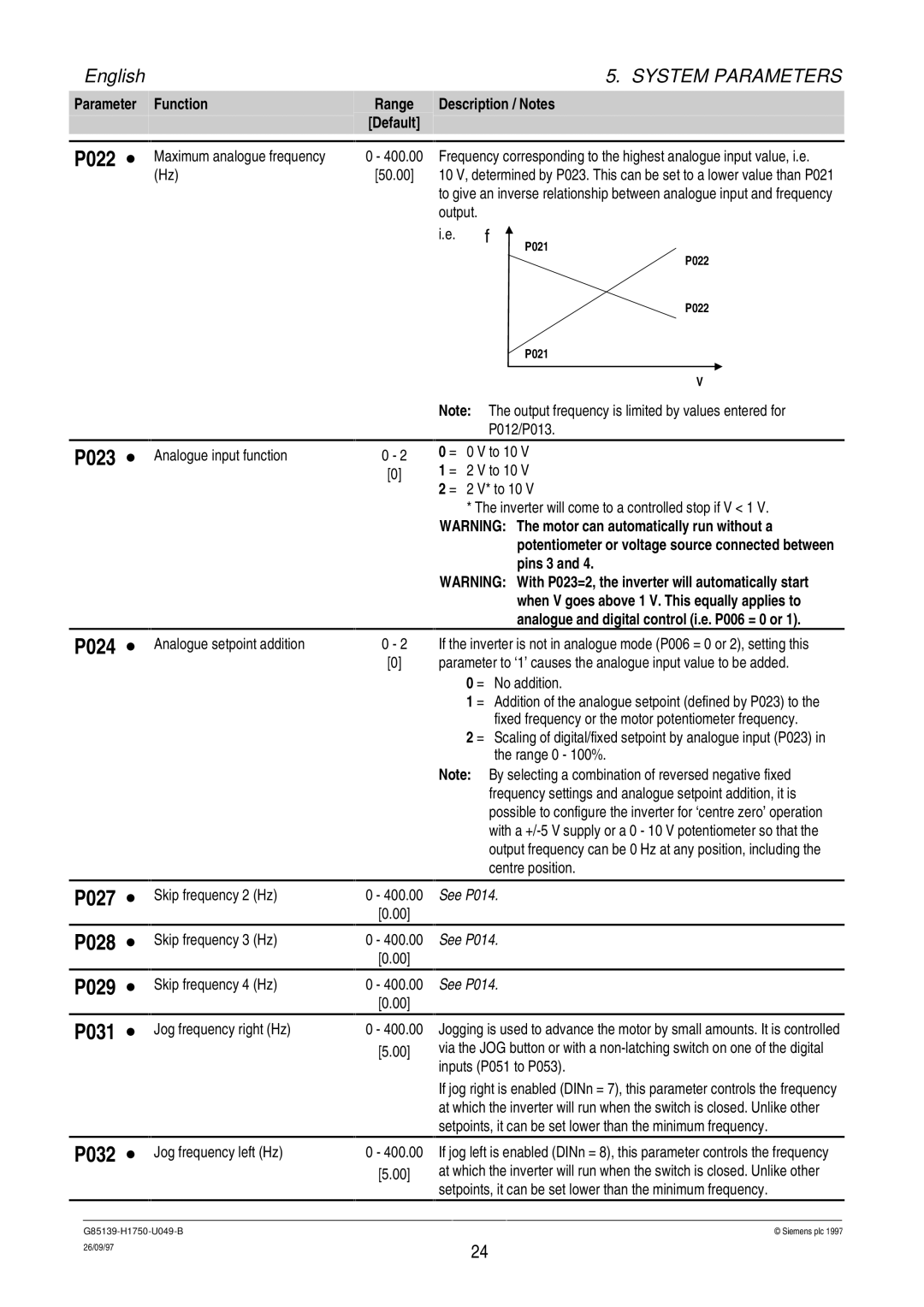
P022 ∙ |
| Maximum analogue frequency | 0 - 400.00 |
| Frequency corresponding to the highest analogue input value, i.e. | ||||
|
| (Hz) | [50.00] |
| 10 V, determined by P023. This can be set to a lower value than P021 | ||||
|
|
|
|
|
| to give an inverse relationship between analogue input and frequency | |||
|
|
|
|
|
| output. |
|
|
|
|
|
|
|
|
| i.e. | f | ||
|
|
|
|
|
|
|
| P021 | |
|
|
|
|
|
|
|
| P022 | |
|
|
|
|
|
|
|
| P022 | |
|
|
|
|
|
|
|
| P021 | |
|
|
|
|
|
|
|
|
|
|
|
|
|
|
|
|
|
| V | |
|
|
|
|
|
| Note: | The output frequency is limited by values entered for | ||
|
|
|
|
|
|
| P012/P013. | ||
P023 ∙
P024 ∙
Analogue input function
Analogue setpoint addition
0 - 2
[0]
0 - 2
[0]
0 = 0 V to 10 V
1 = 2 V to 10 V
2 = 2 V* to 10 V
*The inverter will come to a controlled stop if V < 1 V.
WARNING: The motor can automatically run without a potentiometer or voltage source connected between pins 3 and 4.
WARNING: With P023=2, the inverter will automatically start when V goes above 1 V. This equally applies to analogue and digital control (i.e. P006 = 0 or 1).
If the inverter is not in analogue mode (P006 = 0 or 2), setting this parameter to ‘1’ causes the analogue input value to be added.
0 = No addition.
1 = Addition of the analogue setpoint (defined by P023) to the fixed frequency or the motor potentiometer frequency.
2 = Scaling of digital/fixed setpoint by analogue input (P023) in the range 0 - 100%.
Note: By selecting a combination of reversed negative fixed frequency settings and analogue setpoint addition, it is possible to configure the inverter for ‘centre zero’ operation with a
P027 ∙
P028 ∙
P029 ∙
P031 ∙
P032 ∙
Skip frequency 2 (Hz)
Skip frequency 3 (Hz)
Skip frequency 4 (Hz)
Jog frequency right (Hz)
Jog frequency left (Hz)
0 - 400.00
[0.00]
0 - 400.00
[0.00]
0 - 400.00
[0.00]
0 - 400.00
[5.00]
0 - 400.00
[5.00]
See P014.
See P014.
See P014.
Jogging is used to advance the motor by small amounts. It is controlled via the JOG button or with a
If jog right is enabled (DINn = 7), this parameter controls the frequency at which the inverter will run when the switch is closed. Unlike other setpoints, it can be set lower than the minimum frequency.
If jog left is enabled (DINn = 8), this parameter controls the frequency at which the inverter will run when the switch is closed. Unlike other setpoints, it can be set lower than the minimum frequency.
© Siemens plc 1997 | |
26/09/97 | 24 |
|