5. SYSTEM PARAMETERS |
|
|
|
|
|
|
|
|
|
| English | ||
Parameter |
| Function |
| Range |
| Description / Notes | |||||||
|
|
|
| [Default] |
|
|
|
|
|
|
|
|
|
|
|
|
|
|
|
|
|
|
|
|
| ||
|
|
|
|
|
|
|
|
|
|
|
|
|
|
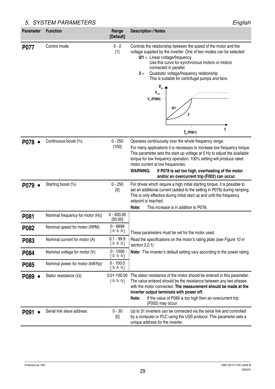
P077 |
| Control mode | 0 - 2 |
| Controls the relationship between the speed of the motor and the | ||||||||
|
|
| [1] |
| voltage supplied by the inverter. One of two modes can be selected: | ||||||||
|
|
|
|
|
| 0/1 = Linear voltage/frequency | |||||||
|
|
|
|
|
| Use this curve for synchronous motors or motors | |||||||
|
|
|
|
|
| connected in parallel. | |||||||
|
|
|
|
|
| 2 = Quadratic voltage/frequency relationship | |||||||
|
|
|
|
|
| This is suitable for centrifugal pumps and fans. | |||||||
|
|
|
|
|
| VN |
| ||||||
|
|
|
|
|
| Vmax |
|
| |||||
|
|
|
|
|
|
|
|
|
|
|
| ||
|
|
|
|
|
| VN (P084) |
|
|
|
|
| ||
|
|
|
|
|
|
|
|
|
| ||||
|
|
|
|
|
|
| 0/1 |
|
|
| |||
|
|
|
|
|
|
| 2 |
|
|
| |||
|
|
|
|
|
|
|
|
|
|
|
|
|
|
|
|
|
|
|
|
|
|
|
|
| f | ||
|
|
|
|
|
|
|
|
|
|
| |||
|
|
|
|
|
|
|
|
|
| fN (P081) | |||
P078 ∙ Continuous boost (%) | 0 - 250 |
| [100] |
Operates continuously over the whole frequency range.
For many applications it is necessary to increase low frequency torque. This parameter sets the
P079 ∙
P081
P082
P083
P084
P085
P089 ∙
P091 ∙
|
|
|
| WARNING: | If P078 is set too high, overheating of the motor | |
|
|
|
|
|
| and/or an overcurrent trip (F002) can occur. |
|
|
|
|
| ||
Starting boost (%) | 0 - 250 |
| For drives which require a high initial starting torque, it is possible to | |||
| [0] |
| set an additional current (added to the setting in P078) during ramping. | |||
|
|
|
| This is only effective during initial start up and until the frequency | ||
|
|
|
| setpoint is reached. | ||
|
|
|
| Note: | This increase is in addition to P078. | |
|
|
|
|
|
| |
Nominal frequency for motor (Hz) | 0 - 400.00 |
|
|
| ||
|
| [50.00] |
|
|
|
|
Nominal speed for motor (RPM) | 0 - 9999 |
|
|
| ||
|
| [ | ] | These parameters must be set for the motor used. | ||
Nominal current for motor (A) | 0.1 - 99.9 | Read the specifications on the motor’s rating plate (see Figure 10 in | ||||
|
| [ | ] | section 3.2.1). |
| |
Nominal voltage for motor (V) | 0 - 1000 | Note: The inverter’s default setting vary according to the power rating. | ||||
|
| [ | ] |
|
|
|
Nominal power for motor (kW/hp) | 0 - 100.0 |
|
|
| ||
|
| [ | ] |
|
|
|
Stator resistance (Ω) | The stator resistance of the motor should be entered in this parameter. | |||||
| [ | ] | The value entered should be the resistance between any two phases | |||
|
|
|
| with the motor connected. The measurement should be made at the | ||
|
|
|
| inverter output terminals with power off. | ||
|
|
|
| Note: | If the value of P089 is too high then an overcurrent trip | |
|
|
|
|
| (F002) may occur. | |
|
|
|
|
| ||
Serial link slave address | 0 - 30 |
| Up to 31 inverters can be connected via the serial link and controlled | |||
| [0] |
| by a computer or PLC using the USS protocol. This parameter sets a | |||
|
|
|
| unique address for the inverter. | ||
|
|
|
|
|
|
|
© Siemens plc 1997G85139-H1750-U049-B
29 | 26/09/97 |
|