5. SYSTEM PARAMETERS |
|
|
| English | ||
Parameter |
| Function |
| Range |
| Description / Notes |
|
|
|
| [Default] |
|
|
|
|
|
|
| ||
|
|
|
|
|
|
|
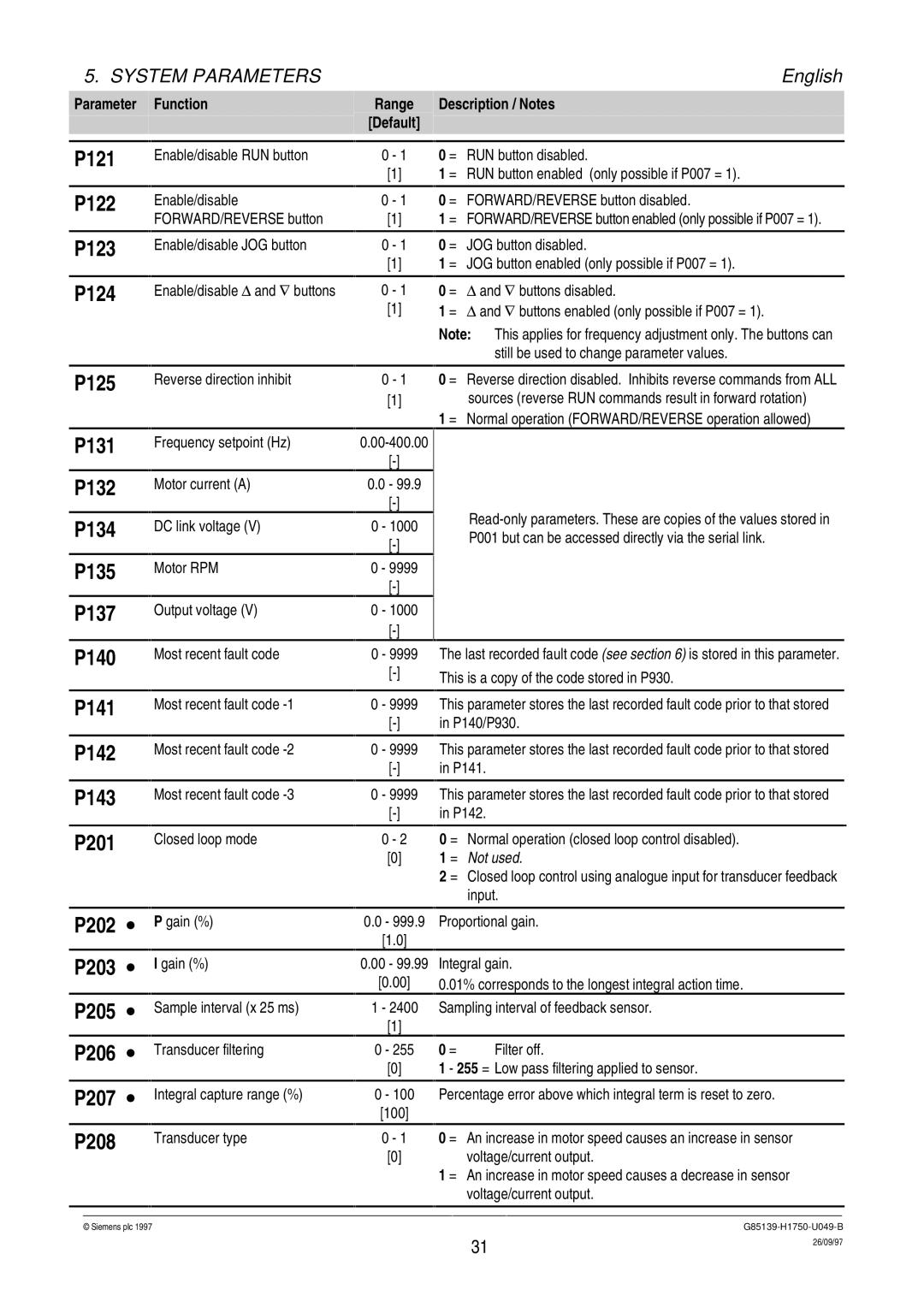
P121 |
| Enable/disable RUN button | 0 - 1 |
| 0 = RUN button disabled. | |
|
|
|
| [1] |
| 1 = RUN button enabled (only possible if P007 = 1). |
P122 |
| Enable/disable | 0 - 1 |
| 0 = FORWARD/REVERSE button disabled. | |
|
| FORWARD/REVERSE button |
| [1] |
| 1 = FORWARD/REVERSE button enabled (only possible if P007 = 1). |
P123 |
| Enable/disable JOG button | 0 - 1 |
| 0 = JOG button disabled. | |
|
|
|
| [1] |
| 1 = JOG button enabled (only possible if P007 = 1). |
P124 |
| Enable/disable Δ and ∇ buttons | 0 - 1 |
| 0 = Δ and ∇ buttons disabled. | |
|
|
| [1] |
| 1 = Δ and ∇ buttons enabled (only possible if P007 = 1). | |
|
|
|
|
|
| Note: This applies for frequency adjustment only. The buttons can |
|
|
|
|
|
| still be used to change parameter values. |
|
|
|
|
|
|
|
P125 |
| Reverse direction inhibit | 0 - 1 |
| 0 = Reverse direction disabled. Inhibits reverse commands from ALL | |
|
|
| [1] |
| sources (reverse RUN commands result in forward rotation) | |
1 = Normal operation (FORWARD/REVERSE operation allowed)
P131
P132
P134
P135
P137
P140
P141
P142
P143
P201
P202 ∙
P203 ∙
P205 ∙
P206 ∙
P207 ∙
P208
Frequency setpoint (Hz)
Motor current (A)
DC link voltage (V)
Motor RPM
Output voltage (V)
Most recent fault code
Most recent fault code
Most recent fault code
Most recent fault code
Closed loop mode
P gain (%)
I gain (%)
Sample interval (x 25 ms)
Transducer filtering
Integral capture range (%)
Transducer type
0.0 - 99.9 |
|
| |
|
| ||
0 | - 1000 |
| |
| P001 but can be accessed directly via the serial link. | ||
|
| ||
|
|
| |
0 - 9999 |
|
| |
|
|
| |
0 | - 1000 |
|
|
|
|
| |
0 | - 9999 |
| The last recorded fault code (see section 6) is stored in this parameter. |
|
| This is a copy of the code stored in P930. | |
|
|
| |
|
|
|
|
0 | - 9999 |
| This parameter stores the last recorded fault code prior to that stored |
|
| in P140/P930. | |
|
|
|
|
0 | - 9999 |
| This parameter stores the last recorded fault code prior to that stored |
|
| in P141. | |
|
|
|
|
0 | - 9999 |
| This parameter stores the last recorded fault code prior to that stored |
|
| in P142. | |
|
|
|
|
| 0 - 2 |
| 0 = Normal operation (closed loop control disabled). |
[0]1 = Not used.
2 = Closed loop control using analogue input for transducer feedback input.
0.0- 999.9 Proportional gain.
[1.0]
0.00 - 99.99 |
| Integral gain. | |
[0.00] |
| 0.01% corresponds to the longest integral action time. | |
1 - 2400 |
| Sampling interval of feedback sensor. | |
[1] |
|
|
|
0 - 255 | 0 = | Filter off. | |
[0]1 - 255 = Low pass filtering applied to sensor.
0 - 100 Percentage error above which integral term is reset to zero. [100]
0 - 1 0 = An increase in motor speed causes an increase in sensor
[0]voltage/current output.
1= An increase in motor speed causes a decrease in sensor voltage/current output.
© Siemens plc 1997G85139-H1750-U049-B
31 | 26/09/97 |
|