English | 2. INSTALLATION |
2.3.2 Power and Motor Connections - Frame Size B
The terminal arrangement for frame size B is identical to frame size A (see Figure 3). However, before the wires can be connected to the terminal blocks, you must lower the terminal access panel and secure the cables to the gland plate.
Refer to Figures 3 and 4. Proceed as follows:
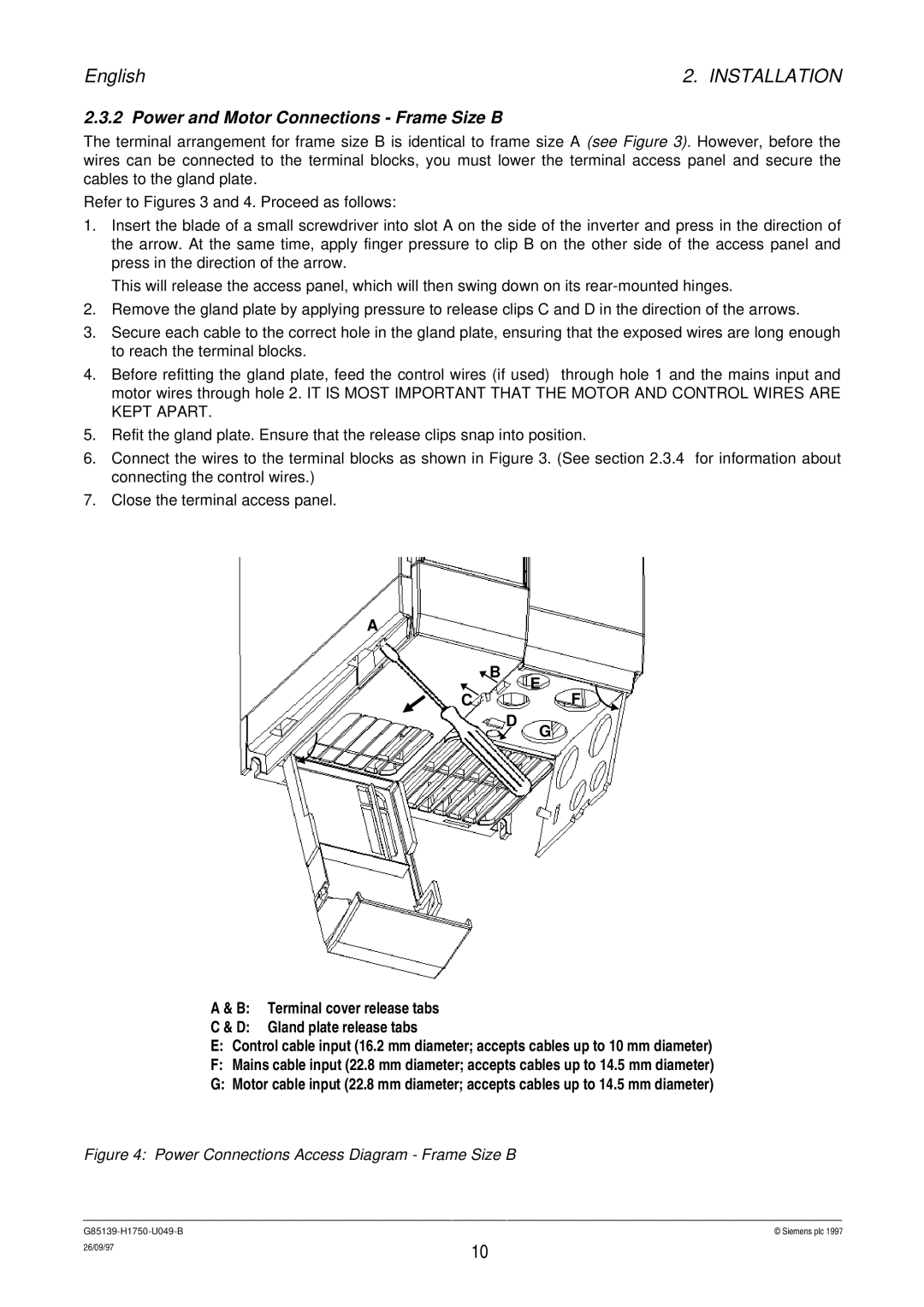
1.Insert the blade of a small screwdriver into slot A on the side of the inverter and press in the direction of the arrow. At the same time, apply finger pressure to clip B on the other side of the access panel and press in the direction of the arrow.
This will release the access panel, which will then swing down on its
2.Remove the gland plate by applying pressure to release clips C and D in the direction of the arrows.
3.Secure each cable to the correct hole in the gland plate, ensuring that the exposed wires are long enough to reach the terminal blocks.
4.Before refitting the gland plate, feed the control wires (if used) through hole 1 and the mains input and motor wires through hole 2. IT IS MOST IMPORTANT THAT THE MOTOR AND CONTROL WIRES ARE KEPT APART.
5.Refit the gland plate. Ensure that the release clips snap into position.
6.Connect the wires to the terminal blocks as shown in Figure 3. (See section 2.3.4 for information about connecting the control wires.)
7.Close the terminal access panel.
A
![]() B
B
E
CF
D
A & B: Terminal cover release tabs
C & D: Gland plate release tabs
G
E:Control cable input (16.2 mm diameter; accepts cables up to 10 mm diameter)
F:Mains cable input (22.8 mm diameter; accepts cables up to 14.5 mm diameter)
G:Motor cable input (22.8 mm diameter; accepts cables up to 14.5 mm diameter)
Figure 4: Power Connections Access Diagram - Frame Size B
© Siemens plc 1997 | |
26/09/97 | 10 |
|