2. INSTALLATION | English |
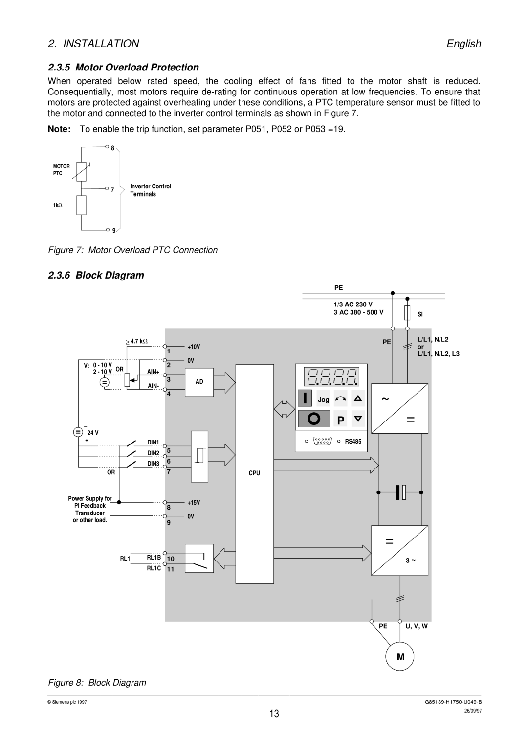
2.3.5 Motor Overload Protection
When operated below rated speed, the cooling effect of fans fitted to the motor shaft is reduced. Consequentially, most motors require
Note: To enable the trip function, set parameter P051, P052 or P053 =19.
![]()
![]() 8
8
MOTOR
PTC
![]() 7
7
1kΩ
Inverter Control Terminals
![]() 9
9 ![]()
Figure 7: Motor Overload PTC Connection
2.3.6 Block Diagram
| ≥ | 4.7 kΩ |
| +10V |
|
|
| 1 | |
|
|
|
| |
V: 0 - 10 V |
|
| 2 | 0V |
OR | AIN+ |
| ||
2 - 10 V |
|
| ||
|
| AIN- | 3 | AD |
|
|
| ||
|
|
|
| |
|
|
| 4 |
|
– |
|
|
|
|
24 V |
|
|
|
|
+ |
| DIN1 |
|
|
|
|
|
| |
|
| DIN2 | 5 |
|
|
|
|
| |
|
| DIN3 | 6 |
|
|
|
|
| |
OR |
|
| 7 |
|
Power Supply for |
|
|
| +15V |
PI Feedback |
|
| 8 | |
|
|
| ||
Transducer |
|
|
| 0V |
or other load. |
|
| 9 | |
|
|
| ||
|
|
|
| |
| RL1 | RL1B | 10 |
|
|
| RL1C | 11 |
|
| PE |
|
| 1/3 AC 230 V |
|
| 3 AC 380 - 500 V | SI |
| PE | L/L1, N/L2 |
| or | |
|
| |
|
| L/L1, N/L2, L3 |
Jog | ~ |
|
|
| |
| P |
|
| RS485 |
|
CPU |
|
|
|
| 3 ~ |
PE
U, V, W
|
| M |
Figure 8: Block Diagram |
|
|
© Siemens plc 1997 |
| |
| 13 | 26/09/97 |
|
|