5. SYSTEM PARAMETERS
Parameter |
| Function | Range |
|
|
| [Default] |
|
|
| |
|
|
|
|
P061 |
| Selection relay output RL1 | 0 - 13 |
|
| [6] | |
|
|
|
P062 |
| 0 - 4 | ||
|
| control | [0] | |
|
|
|
|
|
P063 |
| External brake release delay | 0 - 20.0 | |
|
| (seconds) | [1.0] | |
|
|
|
|
|
P064 |
| External brake stopping time | 0 - 20.0 | |
|
| (seconds) | [1.0] | |
English
Description / Notes
Value | Relay function | Active 3 | |
| 0 | No function assigned (relay not active) | Low |
| 1 | Inverter is running | High |
| 2 | Inverter frequency 0.0 Hz | Low |
| 3 | Motor run right has been selected | High |
| 4 | External brake on (see parameters P063/P064) | Low |
| 5 | Inverter frequency less than or equal to minimum | Low |
|
| frequency |
|
| 6 | Fault indication 1 | Low |
| 7 | Inverter frequency greater than or equal to setpoint | High |
| 8 | Warning active 2 | Low |
| 9 | Output current greater than or equal to P065 | High |
| 10 | Motor current limit (warning) 2 | Low |
| 11 | Motor over temperature (warning) 2 | Low |
| 12 | Closed loop motor LOW speed limit | High |
| 13 | Closed loop motor HIGH speed limit | High |
1 | Inverter switches off (see parameter P930 and section 6). |
| |
2 |
| ||
|
|
| |
Inverter does not switch off (see parameter P931).
3‘Active low’ = relay OPEN. ‘Active high’ = relay CLOSED.
This operates in the same manner as the external brake control (described in P063/P064), except that the relay is not activated.
0 = Normal stop mode
1 - 3 = Do not use
4 = Combination stop mode
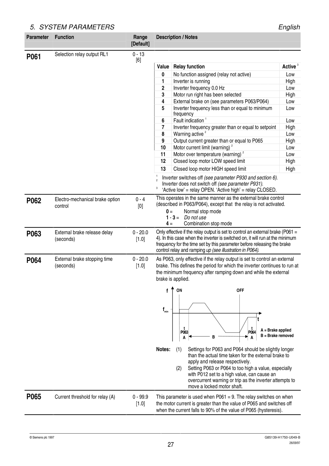
Only effective if the relay output is set to control an external brake (P061 = 4). In this case when the inverter is switched on, it will run at the minimum frequency for the time set by this parameter before releasing the brake control relay and ramping up (see illustration in P064).
As P063, only effective if the relay output is set to control an external brake. This defines the period for which the inverter continues to run at the minimum frequency after ramping down and while the external brake is applied.
f | ON | OFF |
fmin
|
|
|
|
|
|
| t |
|
t |
|
|
|
| t |
| ||
|
|
|
|
|
| A = Brake applied | ||
P063 |
|
|
|
| P064 |
|
| |
| B |
|
|
|
| B = Brake removed | ||
A |
|
|
| A |
|
| ||
|
|
|
| |||||
|
|
|
|
|
|
Notes: (1) Settings for P063 and P064 should be slightly longer
|
|
|
|
|
| than the actual time taken for the external brake to |
|
|
|
|
|
| apply and release respectively. |
|
|
|
|
|
| (2) Setting P063 or P064 to too high a value, especially |
|
|
|
|
|
| with P012 set to a high value, can cause an |
|
|
|
|
|
| overcurrent warning or trip as the inverter attempts to |
|
|
|
|
|
| move a locked motor shaft. |
P065 |
| Current threshold for relay (A) | 0 - 99.9 |
| This parameter is used when P061 = 9. The relay switches on when | |
|
|
| [1.0] |
| the motor current is greater than the value of P065 and switches off | |
|
|
|
|
|
| when the current falls to 90% of the value of P065 (hysteresis). |
|
|
|
|
|
|
|
© Siemens plc 1997G85139-H1750-U049-B
27 | 26/09/97 |
|