TP177B specifications
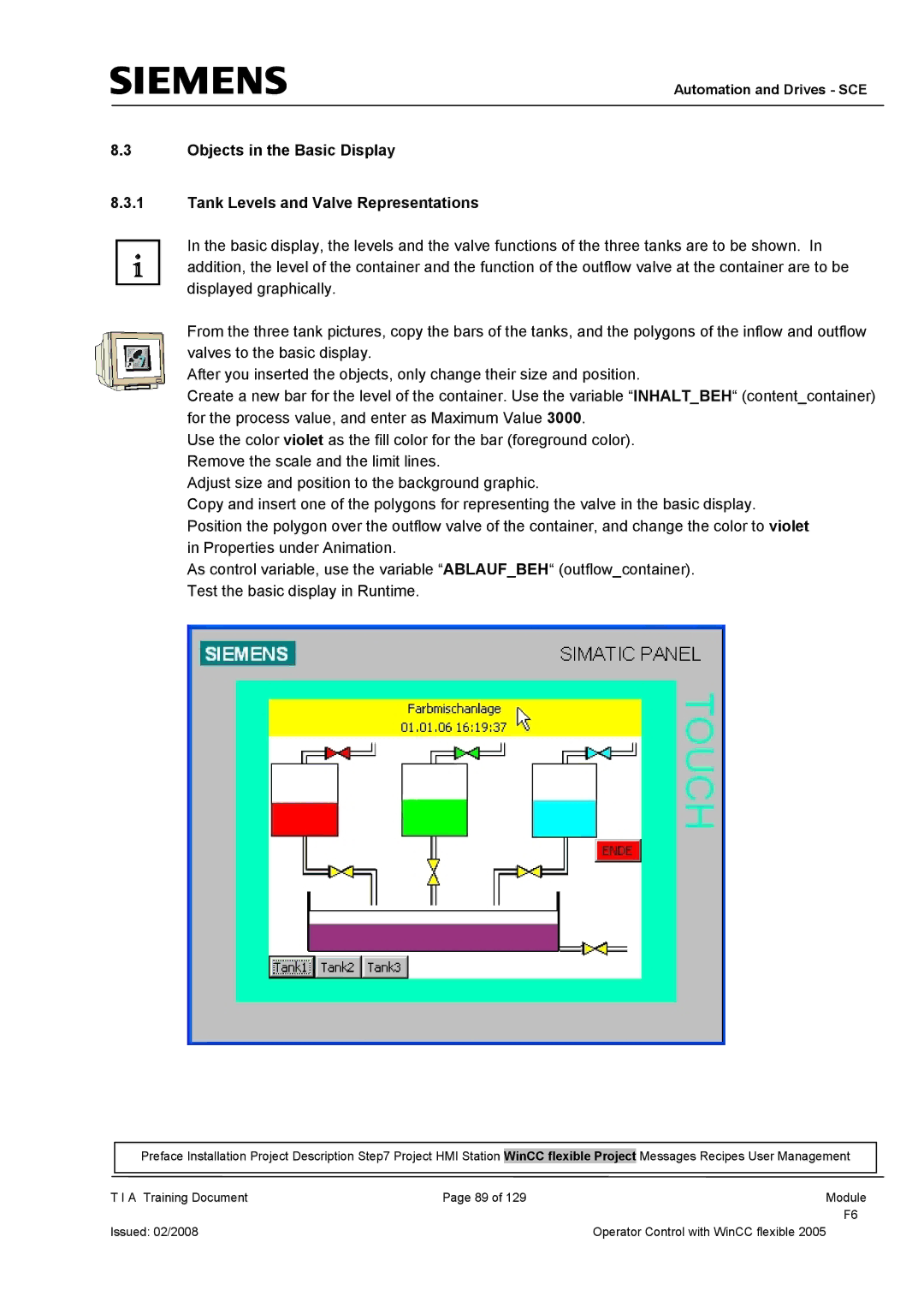
The Siemens TP177B is a compact, user-friendly operator panel designed for a wide range of industrial applications, including automation and process control. As part of Siemens’ HMI (Human-Machine Interface) portfolio, the TP177B integrates seamlessly with various PLCs (Programmable Logic Controllers) and is particularly popular in environments where real-time monitoring and control are essential.One of the standout features of the TP177B is its 7-inch TFT color display, which allows for clear visualization of process data and operational tasks. The touch-sensitive screen enables intuitive navigation through menus and options, enhancing user interactivity. With a resolution of 800x480 pixels, operators benefit from sharp graphics and detailed information, which are crucial for effective decision-making in industrial settings.
The TP177B employs a range of communication protocols, including PROFINET and MPI, facilitating straightforward connectivity with different Siemens PLCs as well as third-party devices. This flexibility allows for the integration of the panel within existing systems, making it versatile for various automation applications.
In terms of construction, the TP177B boasts a robust design with an IP65 rating, making it suitable for harsh industrial environments. This durability ensures that it can withstand dust, moisture, and temperature fluctuations, thus contributing to the longevity of the panel in operational settings.
Another key characteristic of the TP177B is its powerful software support. The panel is compatible with Siemens’ WinCC Flexible software, enabling users to design custom screens, dashboards, and templates tailored to specific operational needs. This capability allows for the optimization of user interfaces, ensuring that operators can access critical information quickly and efficiently.
The TP177B also supports various input options, including the ability to utilize soft keys and function keys, enhancing usability. Furthermore, it features expandable memory for storing templates and visualization projects, ensuring that future upgrades and modifications are hassle-free.
Overall, the Siemens TP177B is a dynamic operator panel that combines user-friendly design with robust functionality and durability. Its comprehensive features make it an indispensable tool for industrial automation, providing operators with the necessary tools to manage processes effectively and efficiently. Whether used in manufacturing, energy, or other sectors, the TP177B stands out as a reliable choice for enhancing operational productivity.

