Chapter 5 — Troubleshooting
5 Troubleshooting
Several hardware diagnostics capabilities have been implemented using the LED indicator lights on the front of the
5.1LED Locations
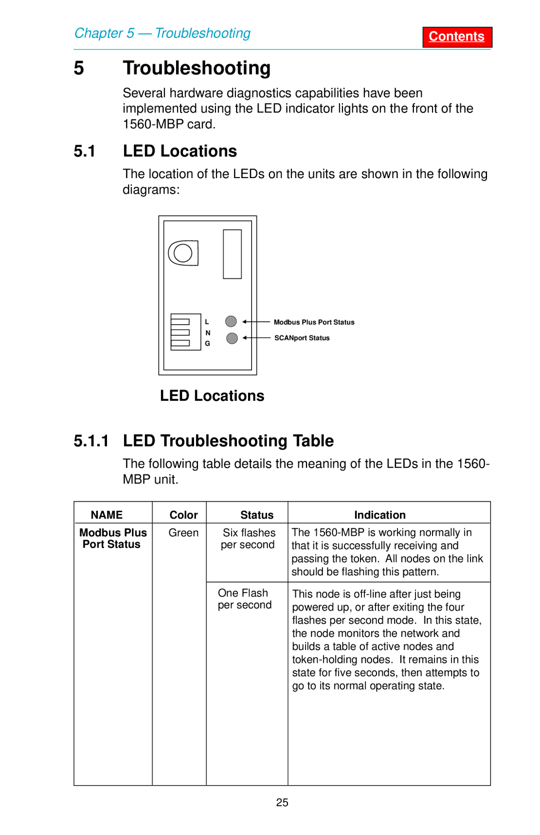
The location of the LEDs on the units are shown in the following diagrams:
L |
| Modbus Plus Port Status |
|
N
G
SCANport Status
LED Locations
5.1.1 LED Troubleshooting Table
The following table details the meaning of the LEDs in the 1560- MBP unit.
NAME | Color | Status | Indication |
|
|
|
|
Modbus Plus | Green | Six flashes | The |
Port Status |
| per second | that it is successfully receiving and |
|
|
| passing the token. All nodes on the link |
|
|
| should be flashing this pattern. |
|
|
|
|
|
| One Flash | This node is |
|
| per second | powered up, or after exiting the four |
|
|
| flashes per second mode. In this state, |
|
|
| the node monitors the network and |
|
|
| builds a table of active nodes and |
|
|
| |
|
|
| state for five seconds, then attempts to |
|
|
| go to its normal operating state. |
|
|
|
|
25