Appendix B — Device Specific Hints
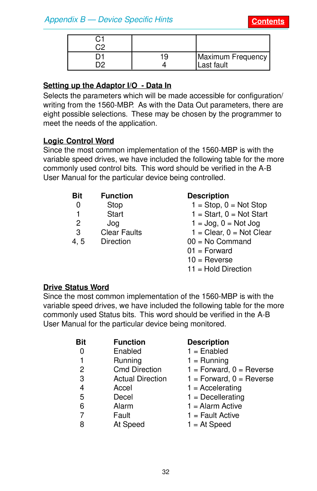
C1 |
|
|
|
C2 |
|
|
|
D1 | 19 | Maximum Frequency |
|
D2 | 4 | Last fault | |
Setting up the Adaptor I/O - Data In
Selects the parameters which will be made accessible for configuration/ writing from the
Logic Control Word
Since the most common implementation of the
Bit | Function | Description | |
0 | Stop | 1 | = Stop, 0 = Not Stop |
1 | Start | 1 | = Start, 0 = Not Start |
2 | Jog | 1 | = Jog, 0 = Not Jog |
3 | Clear Faults | 1 | = Clear, 0 = Not Clear |
4, 5 | Direction | 00 | = No Command |
|
| 01 | = Forward |
|
| 10 | = Reverse |
|
| 11 | = Hold Direction |
Drive Status Word
Since the most common implementation of the
Bit | Function | Description | |
0 | Enabled | 1 | = Enabled |
1 | Running | 1 | = Running |
2 | Cmd Direction | 1 | = Forward, 0 = Reverse |
3 | Actual Direction | 1 | = Forward, 0 = Reverse |
4 | Accel | 1 = Accelerating | |
5 | Decel | 1 | = Decellerating |
6 | Alarm | 1 = Alarm Active | |
7 | Fault | 1 = Fault Active | |
8 | At Speed | 1 = At Speed | |
32