SMC Networks 1560 user manual Host Issued Write Commands Mstr Type

Models: 1560

1 44
Download 44 pages 55.53 Kb
Page 18
Image 18

Chapter 4 — Programming Considerations

In the example (at the bottom of the previous page) the 1560-MBP responding at Node 37 would retrieve its control and reference values from the 8th and 9th words of the Global Data block. In the Host PLC we have placed this data in registers 40418 and 40419, as this corresponds to the 8th and 9th position in the Global Data packet.

4.1.2 Host Issued Write Commands - MSTR Type 1

If the Global Data Control Mode is not enabled, the
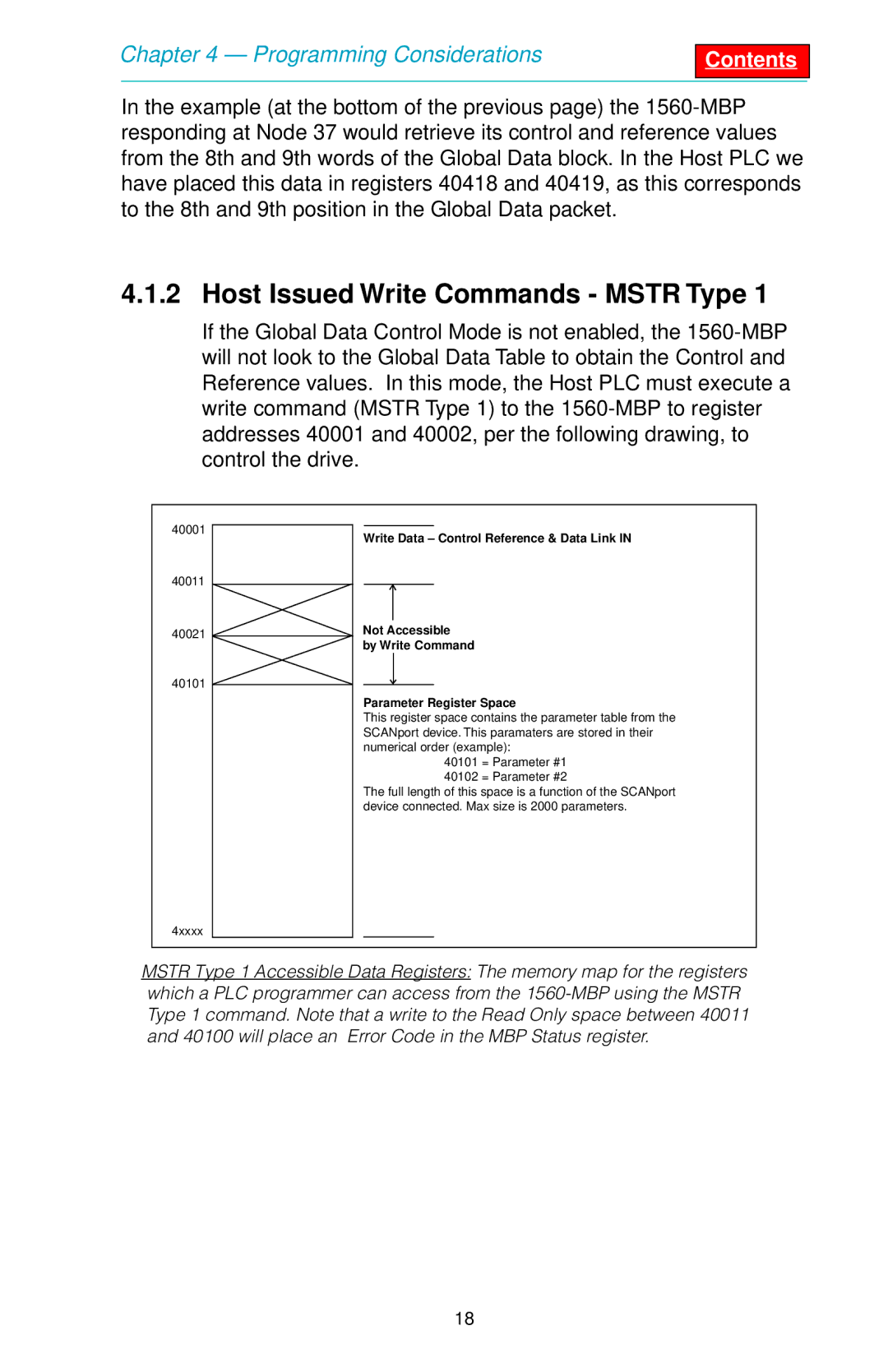
 1560-MBP will not look to the Global Data Table to obtain the Control and Reference values. In this mode, the Host PLC must execute a write command (MSTR Type 1) to the 1560-MBP to register addresses 40001 and 40002, per the following drawing, to control the drive.

40001

40011

40021

40101

4xxxx

Write Data – Control Reference & Data Link IN

Not Accessible

by Write Command

Parameter Register Space

This register space contains the parameter table from the SCANport device. This paramaters are stored in their numerical order (example):

40101 = Parameter #1

40102 = Parameter #2

The full length of this space is a function of the SCANport device connected. Max size is 2000 parameters.

MSTR Type 1 Accessible Data Registers: The memory map for the registers which a PLC programmer can access from the 1560-MBP using the MSTR Type 1 command. Note that a write to the Read Only space between 40011 and 40100 will place an Error Code in the MBP Status register.

18

Page 18
Image 18
SMC Networks 1560 user manual Host Issued Write Commands Mstr Type