Chapter 3 — Hardware Setup
Contents
3 Hardware Setup
3.11560-MBP Card Setup
3.1.1 Connecting Power to the 1560-MBP Card
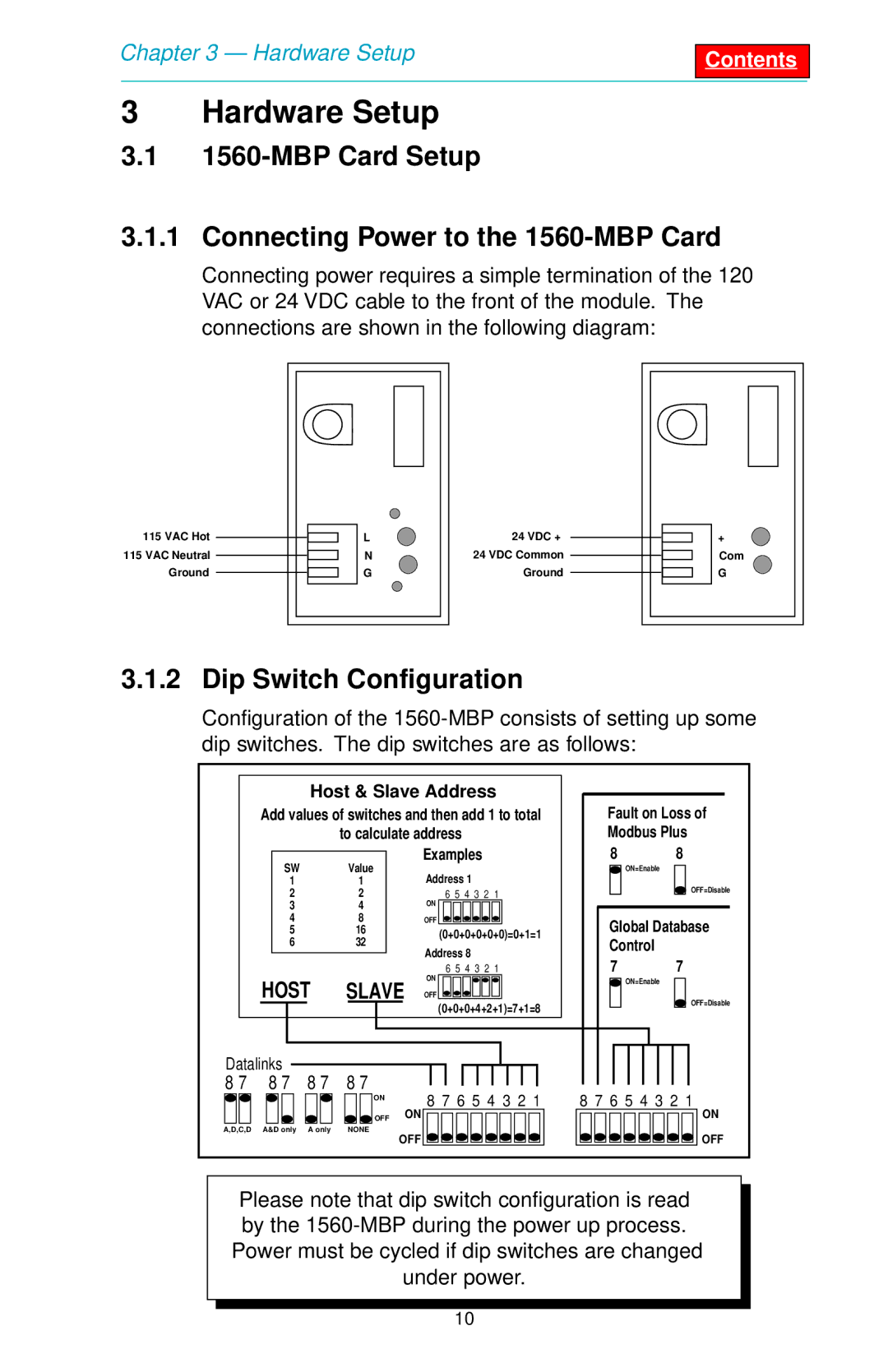
Connecting power requires a simple termination of the 120 VAC or 24 VDC cable to the front of the module. The connections are shown in the following diagram:
115 VAC Hot |
| L | 24 VDC + |
| + |
|
| ||||
115 VAC Neutral |
| N | 24 VDC Common |
| Com |
|
| ||||
Ground |
| G | Ground |
| G |
|
|
3.1.2 Dip Switch Configuration
Configuration of the
Host & Slave Address
Add values of switches and then add 1 to total
to calculate address
|
|
| SW |
|
| Value |
|
| Examples |
|
|
|
|
| |||||||||||
|
|
|
|
|
| Address 1 |
|
|
|
|
|
|
| ||||||||||||
|
|
| 1 |
| 1 |
|
|
|
|
|
|
|
|
|
| ||||||||||
|
|
| 2 |
| 2 |
|
|
| 6 | 5 4 | 3 | 2 1 |
|
|
| ||||||||||
|
|
| 3 |
| 4 |
|
|
| ON |
|
|
|
|
|
|
|
|
|
|
| |||||
|
|
| 4 |
| 8 |
|
|
| OFF |
|
|
|
|
|
|
|
|
|
|
| |||||
|
|
| 5 |
| 16 |
|
|
| (0+0+0+0+0+0)=0+1=1 | ||||||||||||||||
|
|
| 6 |
| 32 |
|
|
| |||||||||||||||||
|
|
|
|
|
|
| Address 8 |
|
|
|
|
|
|
| |||||||||||
|
|
|
|
|
|
|
|
|
|
|
|
|
|
|
|
|
|
| |||||||
|
|
|
|
|
|
|
|
|
|
|
|
|
|
|
|
|
|
| |||||||
|
|
|
|
|
|
|
|
|
|
|
| 6 | 5 4 3 | 2 | 1 |
|
|
| |||||||
|
| HOST | SLAVE | ON |
|
|
|
|
|
|
|
|
|
|
|
| |||||||||
|
| OFF |
|
|
|
|
|
|
|
|
|
|
|
| |||||||||||
|
|
|
|
|
|
|
|
|
|
|
| (0+0+0+4+2+1)=7+1=8 | |||||||||||||
|
|
|
|
|
|
|
|
|
|
|
| ||||||||||||||
|
|
|
|
|
|
|
|
|
|
|
|
|
|
|
|
|
|
|
|
|
|
|
| ||
|
|
|
|
|
|
|
|
|
|
|
|
|
|
|
|
|
|
|
|
|
|
|
|
|
|
Datalinks |
|
|
|
|
|
|
|
|
|
|
|
|
|
|
|
|
|
|
|
|
| ||||
8 7 | 8 7 |
| 8 7 | 8 7 |
|
|
|
|
|
|
|
|
|
|
|
|
|
|
|
|
| ||||
|
|
|
|
|
|
|
|
|
|
|
|
|
|
|
|
| |||||||||
Fault on Loss of Modbus Plus
8 8
ON=Enable
OFF=Disable
Global Database
Control
7 7
ON=Enable
OFF=Disable
|
|
|
|
|
|
|
|
|
|
| ON |
|
|
|
|
|
|
|
|
|
|
| OFF |
A,D,C,D A&D only A only |
| NONE | |||||||||
8 7 6 5 4 3 2 1
ON
OFF ![]()
![]()
![]()
![]()
![]()
![]()
![]()
![]()
8 7 6 5 4 3 2 1
ON
OFF
Please note that dip switch configuration is read by the
10