Appendix B — Device Specific Hints
Appendix B
Device Specific Hints
SMC Dialogue Plus
The SMC Dialogue Plus does not support Datalinks, therefore the configuration of
The version of SMC which was tested (Rev 1.05) had 88 parameters. Each parameter was accessible in the Modbus register listing shown in Appendix A. Note that if one of the 88 parameters is to be changed from a host that the host must enable the EEPROM Storage function by writing a 2 into the Parameter Management parameter (Parameter 17 - Modbus address 40117 ).
SMP 3
The SMP3 does not support Datalinks, therefore the configuration of Datalinks should not include any of the Datalinks Enabled. If a Datalink is enabled, the SCANport Status LED will toggle, indicating an error in the SCANport communications.
The
Variable Speed Drives
In order to enable Frequency control from the
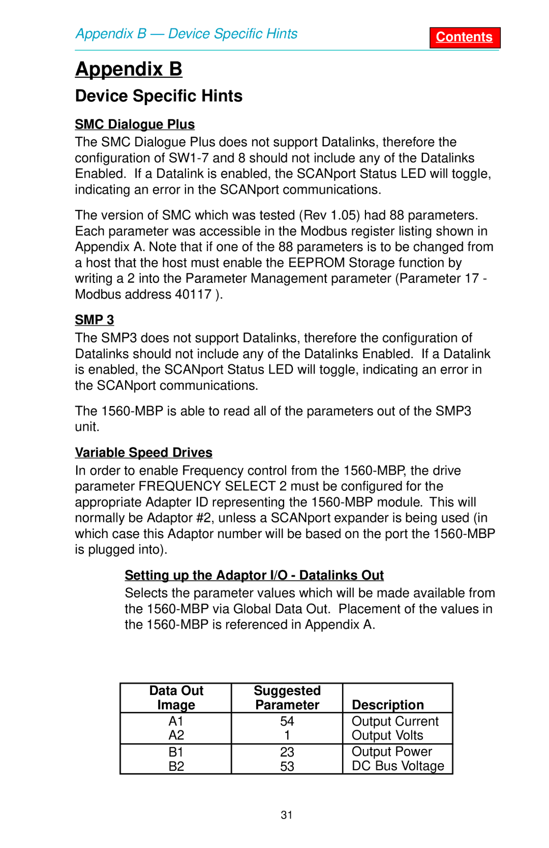
Setting up the Adaptor I/O - Datalinks Out
Selects the parameter values which will be made available from the
Data Out | Suggested |
|
Image | Parameter | Description |
A1 | 54 | Output Current |
A2 | 1 | Output Volts |
B1 | 23 | Output Power |
B2 | 53 | DC Bus Voltage |
31