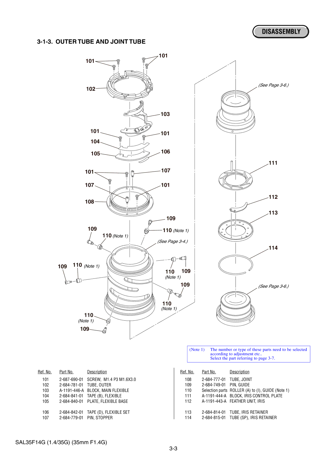
3-1-3. OUTER TUBE AND JOINT TUBE
101
102
101
104
105
101
107
108
109
110 (Note 1)
109110 (Note 1)
110
(Note 1)
109
101
103
101
106
107
101
109
110 (Note 1)
(See Page
110 109
(Note 1)
109
110
(Note 1)
DISASSEMBLY
(See Page
111
112
113
114
(See Page
Ref. No. | Part No. | Description |
101
102
103A-1191-446-A BLOCK, MAIN FLEXIBLE
104
105
106
107
(Note 1) The number or type of these parts need to be selected according to adjustment etc..
Select the part referring to page
Ref. No. | Part No. | Description |
108
109
110Selection parts ROLLER (A) to (I), GUIDE (Note 1)
111A-1191-444-A BLOCK, IRIS CONTROL PLATE
112
113
114
SAL35F14G (1.4/35G) (35mm F1.4G)