For Machines Mfg. Since 8/09 | O P E R A T I O N | SB1024/SB1025/SB1026 |
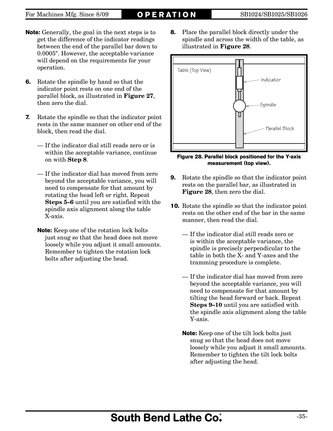
Note: Generally, the goal in the next steps is to | 8. Place the parallel block directly under the | |
| get the difference of the indicator readings | spindle and across the width of the table, as |
| between the end of the parallel bar down to | illustrated in Figure 28. |
| 0.0005". However, the acceptable variance |
|
| will depend on the requirements for your |
|
| operation. | Table (Top View) |
|
| |
6. | Rotate the spindle by hand so that the | Indicator |
| indicator point rests on one end of the |
|
| parallel block, as illustrated in Figure 27, |
|
| then zero the dial. | Spindle |
7. | Rotate the spindle so that the indicator point |
|
| rests in the same manner on other end of the | Parallel Block |
| block, then read the dial. | |
|
| |
| — If the indicator dial still reads zero or is |
|
| within the acceptable variance, continue | Figure 28. Parallel block positioned for the |
| on with Step 8. | |
| measurement (top view). | |
|
| |
— If the indicator dial has moved from zero | 9. | Rotate the spindle so that the indicator point | |
beyond the acceptable variance, you will | |||
| rests on the parallel bar, as illustrated in | ||
need to compensate for that amount by |
| ||
| Figure 28, then zero the dial. | ||
rotating the head left or right. Repeat |
| ||
|
| ||
Steps | 10. | Rotate the spindle so that the indicator point | |
spindle axis alignment along the table | |||
|
|
rests on the other end of the bar in the same | ||
manner, then read the dial. | ||
| ||
Note: Keep one of the rotation lock bolts | — If the indicator dial still reads zero or | |
just snug so that the head does not move | ||
is within the acceptable variance, the | ||
loosely while you adjust it small amounts. | ||
spindle is precisely perpendicular to the | ||
Remember to tighten the rotation lock | ||
table in both the X- and | ||
bolts after adjusting the head. | ||
tramming procedure is complete. | ||
| ||
| — If the indicator dial has moved from zero | |
| beyond the acceptable variance, you will | |
| need to compensate for that amount by | |
| tilting the head forward or back. Repeat | |
| Steps | |
| the spindle axis alignment along the table | |
| ||
| Note: Keep one of the tilt lock bolts just | |
| snug so that the head does not move | |
| loosely while you adjust it small amounts. | |
| Remember to tighten the tilt lock bolts | |
| after adjusting the head. |
