PARTS REMOVAL AND REPLACEMENT
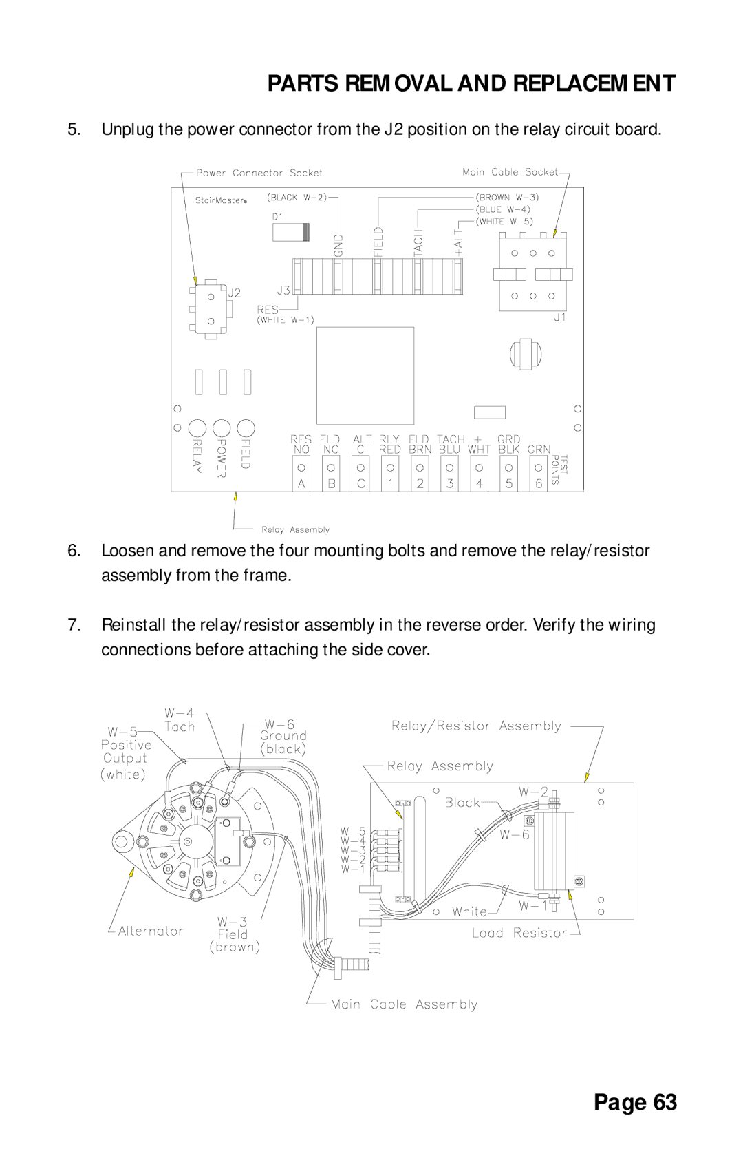
5. Unplug the power connector from the J2 position on the relay circuit board.
6.Loosen and remove the four mounting bolts and remove the relay/resistor assembly from the frame.
7.Reinstall the relay/resistor assembly in the reverse order. Verify the wiring connections before attaching the side cover.
Page 63