SUPERSERVER
5-8 Connector Definitions
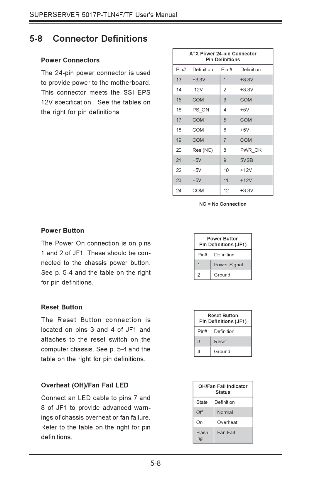
Power Connectors
The
ATX Power
Pin Definitions
Pin# | Definition | Pin # | Definition |
13 | +3.3V |
| +3.3V |
1 | |||
14 |
| +3.3V | |
2 | |||
15 | COM |
| COM |
3 | |||
16 | PS_ON |
| +5V |
4 | |||
17 | COM |
| COM |
5 | |||
18 | COM |
| +5V |
6 | |||
19 | COM |
| COM |
7 | |||
20 | Res (NC) |
| PWR_OK |
8 | |||
21 | +5V |
| 5VSB |
9 | |||
22 | +5V |
| +12V |
10 | |||
23 | +5V | 11 | +12V |
24 | COM | 12 | +3.3V |
|
|
|
|
NC = No Connection
Power Button
The Power On connection is on pins 1 and 2 of JF1. These should be con- nected to the chassis power button. See p.
Reset Button
The Reset Button connection is located on pins 3 and 4 of JF1 and attaches to the reset switch on the computer chassis. See p.
Overheat (OH)/Fan Fail LED
Connect an LED cable to pins 7 and 8 of JF1 to provide advanced warn- ings of chassis overheat or fan failure. Refer to the table on the right for pin definitions.
Power Button
Pin Definitions (JF1)
Pin# Definition
1Power Signal
2Ground
Reset Button
Pin Definitions (JF1)
Pin# Definition
3Reset
4Ground
OH/Fan Fail Indicator
Status
State Definition
Off | Normal | |
On | Overheat | |
Flash- | Fan Fail | |
ing |
| |
|
|