SUPERSERVER
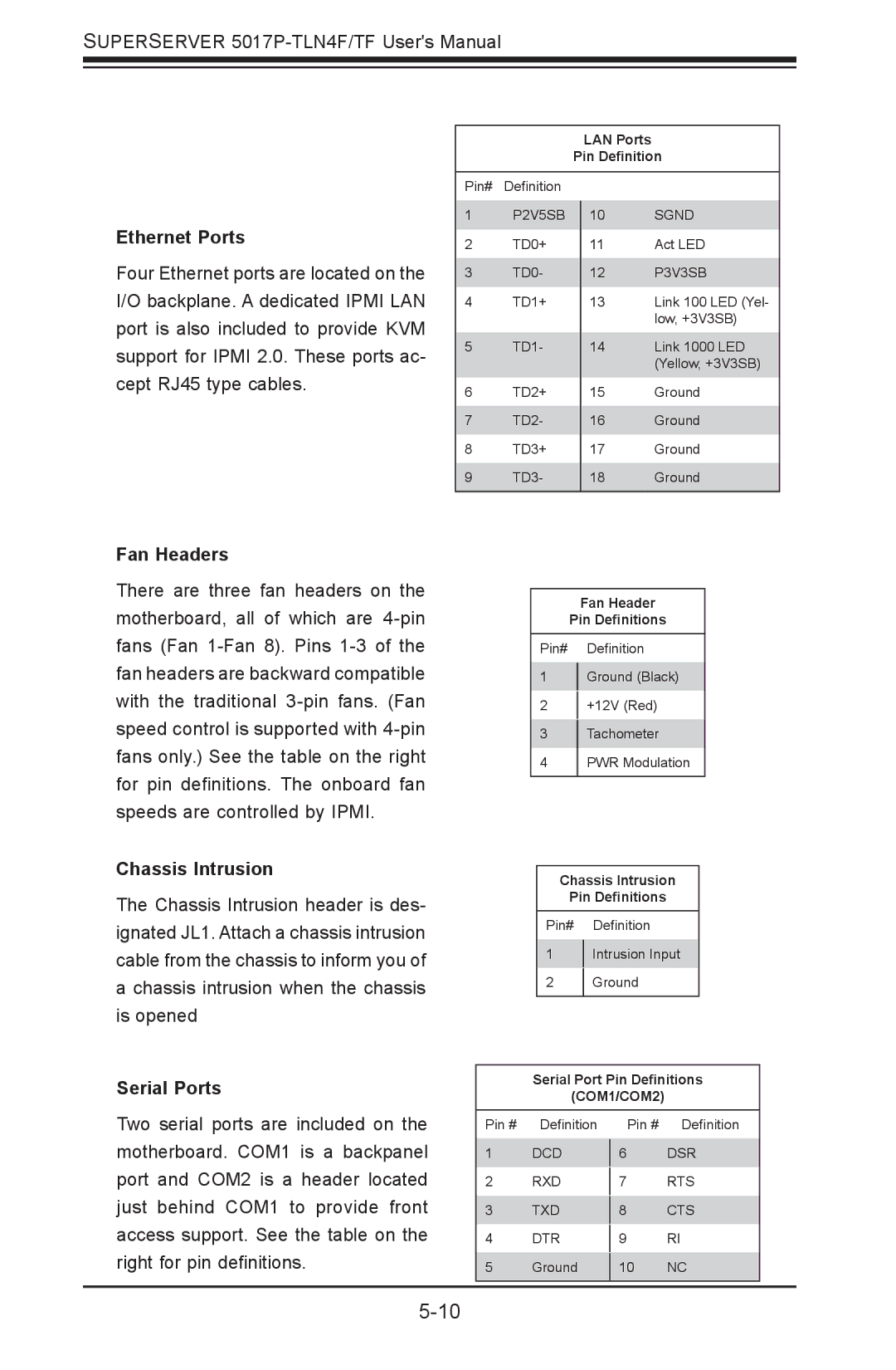
LAN Ports
Pin Definition
Ethernet Ports
Four Ethernet ports are located on the I/O backplane. A dedicated IPMI LAN port is also included to provide KVM support for IPMI 2.0. These ports ac- cept RJ45 type cables.
Pin# Definition
1P2V5SB
2TD0+
3TD0-
4TD1+
5TD1-
6TD2+
7TD2-
8TD3+
9TD3-
10SGND
11Act LED
12P3V3SB
13Link 100 LED (Yel- low, +3V3SB)
14Link 1000 LED (Yellow, +3V3SB)
15Ground
16Ground
17Ground
18Ground
Fan Headers
There are three fan headers on the motherboard, all of which are
Chassis Intrusion
The Chassis Intrusion header is des- ignated JL1. Attach a chassis intrusion cable from the chassis to inform you of a chassis intrusion when the chassis is opened
Serial Ports
Fan Header
Pin Definitions
Pin# Definition
1Ground (Black)
2+12V (Red)
3Tachometer
4PWR Modulation
Chassis Intrusion
Pin Definitions
Pin# Definition
1Intrusion Input
2Ground
Serial Port Pin Definitions
(COM1/COM2)
Two serial ports are included on the motherboard. COM1 is a backpanel port and COM2 is a header located just behind COM1 to provide front access support. See the table on the right for pin definitions.
Pin # Definition
1DCD
2RXD
3TXD
4DTR
5Ground
Pin # Definition
6DSR
7RTS
8CTS
9RI
10NC