SUPERSERVER
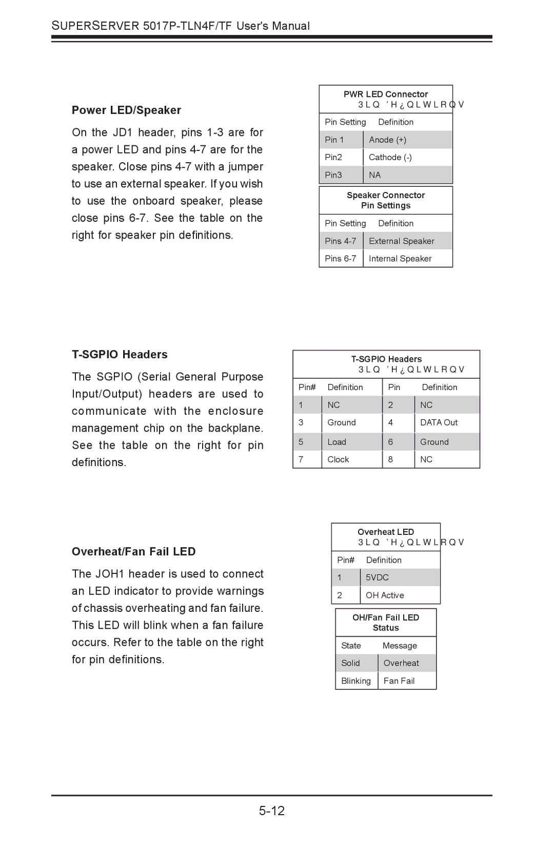
Power LED/Speaker
On the JD1 header, pins 1-3 are for
apower LED and pins
T-SGPIO Headers
The SGPIO (Serial General Purpose
PWR LED Connector
Pin Definitions
Pin Setting | Definition | |
|
| |
Pin 1 |
| Anode (+) |
|
|
|
Pin2 |
| Cathode |
|
|
|
Pin3 |
| NA |
|
|
|
Speaker Connector
Pin Settings
Pin Setting | Definition | |
|
| |
Pins |
| External Speaker |
|
|
|
Pins |
| Internal Speaker |
|
|
|
Pin Definitions
Input/Output) headers are used to communicate with the enclosure management chip on the backplane. See the table on the right for pin definitions.
Pin#
1
3
5
7
Definition
NC
Ground
Load
Clock
Pin Definition
2 NC
4 DATA Out
6Ground
8NC
Overheat/Fan Fail LED
The JOH1 header is used to connect an LED indicator to provide warnings of chassis overheating and fan failure. This LED will blink when a fan failure occurs. Refer to the table on the right for pin definitions.
Overheat LED
Pin Definitions
Pin# Definition
15VDC
2OH Active
OH/Fan Fail LED
Status
State |
| Message |
Solid |
| Overheat |
| ||
Blinking |
| Fan Fail |
| ||
|
|
|
